Monday, December 31, 2012

Happy New Year! May it be a “powerful” one!!

I just want to take this opportunity to thank all of our readers for taking an interest in the Watt’s Up? blog posts. Power-related topics have been a part of our professional careers (and personal lives) for decades and we are both thrilled and honored to be able to share some of what we have learned over the years with you, our readers.

During 2012, we have seen our readership grow by more than 5 times that of 2011! And we hope to see that growth continue during 2013. To make that happen, we would like to hear from you, our readers, about what power-related topics are of greatest interest to you for 2013. Please comment below and we will be happy to post about any power-related issues you bring up!  

Finally, on behalf of Ed Brorein, Matt Carolan, and myself, and all of us at Agilent Technologies, Happy New Year! May 2013 be a “powerful” year for you all!!

Friday, December 21, 2012

Two-quadrant power supplies are better than one!

Back in October, I posted an explanation about what was a bipolar (four-quadrant) power supply (see post here: https://powersupplyblog.tm.agilent.com/2012/10/what-is-bipolar-four-quadrant-power.html). That post covered two-quadrant supplies as well. Last week, while in Lorton, Virginia, I had an opportunity to meet with some of our U.S. Army customers  - engineers working at Fort Belvoir. Many of the engineers worked in the Counter Measures Research Laboratory (CMRL). While they are very careful to not reveal any details about the specifics of the work they do, one of the engineers shared a story with me about two-quadrant operation that is worth repeating.

The story was told while I was providing a demonstration of one of our power supplies, the N6705B DC Power Analyzer (see Figure 1). I was explaining to a group of engineers that some of the 34 power modules that can be installed in the N6705B are two-quadrant power supplies: they can source current and also sink current at one voltage polarity. Other power modules are four-quadrant power supplies: they can source and sink current, and provide positive or negative voltage. This explanation inspired one of the engineers to tell the group that the N6705B helped him solve a problem!


A battery operated device (he did not mention what it was) came into his lab because it was not functioning properly: it had some type of intermittent problem. In an attempt to reproduce the problem, he removed the battery and connected the device’s power input terminals to a power supply on his lab bench. But even after running the device for long periods of time and through all of its operating modes, he was unable to reproduce the intermittent problem.

One of his colleagues suggested he try connecting the device to a two-quadrant power supply installed in the N6705B they owned. The original power supply he was using was a one-quadrant supply – it could source power, but could not absorb power. The battery that normally powers the device can source and sink (absorb) power, so perhaps a power supply that more closely mimicked the behavior of the battery could help uncover the problem. Well, this worked! With the device connected to the two-quadrant power supply in the N6705B, the intermittent problem showed up again proving that it was related to the battery being able to source and sink power – a power supply with similar characteristics was needed. Apparently, the device has a mode in which it momentarily forces current back out of the battery input terminals. That current is normally absorbed by the battery. And during that time, this intermittent problem must show up. During test, a single-quadrant power supply is unable to absorb the power and therefore does not reveal the problem. A two-quadrant power supply can sink the momentary current, and the problem was back, enabling the engineer to track it down and eliminate it! See Figure 2 for an example of the output characteristic of a two-quadrant power supply.

This example demonstrates the importance of choosing a power supply with the right output characteristics for your test. When testing a device or circuit with a power supply, the closer that power supply’s behavior is to the actual power used with the device or circuit, the more you will reveal about the actual performance of your device or circuit.  There are applications in which a two-quadrant power supply will better replicate a battery’s behavior than a single-quadrant power supply, even if you don’t expect the battery to absorb power during test. One CMRL engineer experienced this firsthand.

Monday, December 10, 2012

More on power supply current source-to-sink crossover characteristics


On my earlier posting “Power supply current source-to-sink crossover characteristics” I showed what the effects on the output voltage of a unipolar two-quadrant-power supply were, resulting from the output current on the power supply transitioning between sourcing and sinking. In that example scenario, the power supply was maintaining a constant output voltage and the transitioning between sourcing and sinking current was dictated by the external device connected to and being powered by the power supply. This is perhaps the most common scenario one will encounter that will drive the power supply between sourcing current and sinking current.

Other scenarios do exist that will drive a unipolar two-quadrant power supply to transition between sourcing and sinking output current. One scenario is nearly identical to the earlier posting. However, instead of the device transitioning its voltage between being less and greater than the power supply powering it, the power supply instead transitions its voltage between being less and greater than the active device being normally powered.  A set up for evaluating this scenario on an Agilent N6781A two-quadrant DC source is depicted in Figure 1.


Figure 1: Evaluating current source-to-sink crossover on an N6781A operating in constant voltage

In this scenario having the DC source operating as a voltage source and transitioning between 1.5 and 4.5 volts causes the current to transition between -0.75 and +0.75A.  The voltage and current waveforms captured on an oscilloscope are shown in Figure 2.


Figure 2: Voltage and current waveforms for the set up in Figure 1

The waveforms in Figure 2 are as what should be expected. The actual transition points are where the current waveform passes through zero on the rising and falling edge. An expanded view to the current source-to-sink transition is shown in Figure 3.


Figure 3: Expanded voltage and current waveforms for the set up in Figure 1

As can be seen the voltage ramp transitions smoothly at the threshold point, or zero crossing point, of the current waveform. The reason being is that the DC is maintaining its operation as a voltage source. Its voltage feedback loop is always in control.


Yet one more scenario that will drive a unipolar two-quadrant source to transition between sourcing and sinking current is operate it as a current source and program is current setting between positive and negative values. In this case the device under test that was used is a voltage source.  One real-world example is cycling a rechargeable battery by alternately applying charging and discharging currents to it. The set up for evaluating this scenario, again using an N6781A two-quadrant DC source is depicted in Figure 4.


Figure 4: Evaluating current source-to-sink crossover on an N6781A operating in constant current

For Figure 4 the N6781A was set to operate in constant current and programmed to alternately transition between -0.75A and +0.75A current settings. The resulting voltage and current waveforms are shown in Figure 5.


Figure 5: Voltage and current waveforms for the set up in Figure 4

The waveforms in Figure 5 are as what should be expected. The actual transition points are where the current waveform passes through zero on the rising and falling edge. An expanded view to the current source-to-sink transition is shown in Figure 6.


Figure 6: Expanded voltage and current waveforms for the set up in Figure 4

As the N6781A is operating in current priority the interest is in how well it controls its current while transitioning through the zero-crossing point. As observed in Figure 6 it transitions smoothly through the zero-crossing point. The voltage performance is determined by the DUT, not the N6781A, as the N6781A is operating in constant current.

So what was found here is, for a unipolar two-quadrant DC source, transitioning between sourcing and sinking current should generally be virtually seamless as, under normal circumstances, should remain in either constant voltage or constant current during the entire transition.

Wednesday, December 5, 2012

Power supply current source-to-sink crossover characteristics


A two-quadrant power supply is traditionally one that outputs unipolar voltage but is able to both source as well as sink current. For a positive polarity power source, when sourcing current it is operating in quadrant 1 as a conventional power source. When sinking current it is operating in quadrant 2 as an electronic load. Conversely, a negative polarity two-quadrant  power source operates in quadrants three and four. Further details on power supply operating quadrants are provided in a recent posting here in ‘Watt’s Up?”, What is a bipolar (four-quadrant) power supply? Often a number of questions come up when explaining two-quadrant power supply operation, including:
  • What does it take to get the power supply operating as a voltage source to cross over from sourcing to sinking current?
  • What effect does crossing over from sourcing to sinking current have on the power supply’s output?


For a two-quadrant voltage source to be able to operate in the second quadrant as an electronic load, the device it is normally powering must also be able to source current and power as well as normally draw current and power. Such an arrangement is depicted in Figure 1, where the device is normally a load, represented by a resistance, but also has a charging circuit, represented by a switch and a voltage source with current-limiting series resistance.


Figure 1: Voltage source and example load device arrangement for two-quadrant operation.

There is no particular control on a two-quadrant power supply that one has to change to get it to transition from sourcing current and power to sinking current and power from the device it is normally powering. It is simply when the source voltage is greater than the device’s voltage then the voltage source will be operating in quadrant one sourcing power and when the source voltage is less than the device’s voltage the voltage source will be operating in quadrant two as an electronic load. In figure 1, during charging the load device can source current back out of its input power terminals as long as the charger’s current-limited voltage is greater than the source voltage.

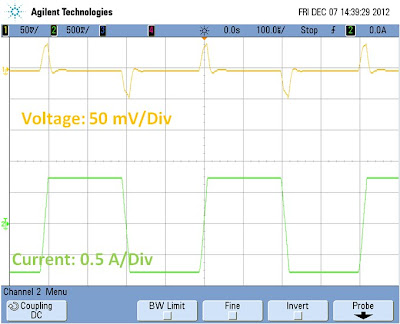
It is assumed that load device’s load and charge currents are lower than the positive and negative current limits of the voltage source so that the voltage source always remains in constant voltage (CV) operation. A step change in current is the most demanding from a transient standpoint, but as the voltage source is always in its constant voltage mode it handle the transition well as its voltage control amplifier is always in control. This is in stark contrast to a mode cross over between voltage and current where different control amplifiers need to exchange control of the power supply’s output. In this later case there can be a large transient while changing modes. See another posting, Why Does My Power Supply Overshoot at Current Limit? Insights on Mode Crossover” for further information on this.  There is a specification given on voltage sources which quantifies the impact one should expect to see from a step change in current going from sourcing current to sinking current, which is its transient voltage response.  A transient voltage response measurement was taken on an N6781A two-quadrant DC source, stepping the load from 0.1 amps to 1.5 amps, roughly 50% of its rated output current.


Figure 2: Agilent N6781A transient voltage response measurement for 0.1A to 1.5A load step

However, the transient voltage response shown in Figure 2 was just for sourcing current. With a well-designed two-quadrant voltage source the transient voltage response should be virtually unchanged for any step change in current load, as long as it falls within the voltage source’s current range.  The transient voltage response for an N6781A was again capture in Figure 3, but now for stepping the load between -0.7A and +0.7A.


Figure 3: Agilent N6781A transient voltage response measurement for -0.7A to +0.7A load step

As can be seen in Figures 2 and 3 the voltage transient response for the N6781A remained unchanged regardless of whether the stepped load current was all positive or swung between positive and negative (sourcing and sinking).

While the transient voltage response addresses the dynamic current loading on the voltage source there is another specification that addresses the static current loading characteristic, which is the DC load regulation or load effect.  This is a very small effect on the order of 0.01% output change for many voltage sources. For example, for the N6781A the load effect in its 6 volt range is 400 microvolts for any load change. In the case of the N6781A being tested here the DC change was the same for both the 0.1 to 1.5 amp step and the -0.7 to +0.7 amp step change.


There are two more scenarios which will cause a two-quadrant power supply transition between current sourcing and sinking.  The first is very similar to above with the two-quadrant power supply operating in constant voltage (CV) mode, but instead of the DUT changing, the power supply changes its voltage level instead.  The final scenario is having the two-quadrant power supply operating in constant current with the DUT being a suitable voltage source that is able to source and sink power as well, like a battery for example. Here the two-quadrant power supply can be programmed to change from a positive current setting to a negative current setting, thus transitioning between sourcing and sinking current again, and its current regulating performance is now a consideration.  Both good topics for future postings!