Showing posts with label current source. Show all posts

Monday, February 9, 2015

Consider using an electronic load for generating fast, high-power current pulses

Often there is the need for generating high-power current pulses, typically of short duration, and having rise and fall times on the order of microseconds. This is a common need when testing many types of power semiconductors, for example.

When looking for a DC power supply capable of generating very fast, high-power current pulses, one will find there are not a lot of options readily available that are capable of addressing their needs. There are specialized products dedicated for specific applications like this; an example of this is Keysight’s B1505A purpose-built semiconductor test equipment. They are capable of generating extremely fast, high-power current pulses.

Apart from specialized products however, DC power supplies generally to not offer this kind of speed when operating in a constant current mode (or current priority mode). One exception that comes to mind that we provide is our N6782A and N6782A DC source measure modules. They can create fast current pulses having just a couple of microseconds of rise and fall time. However, they are limited to 20V, 3A, and 20W of output. Most of the higher power, more general-purpose DC sources are not able to generate these kinds of fast, high-power current pulses and most are really more optimized to operate as voltage sources.

One alternative to consider for generating fast, high-power current pulses when working with general-purpose test equipment is to use an electronic load. You may initially say to yourself “an electronic load is for drawing pulses of current, not sourcing them!” but when coupled to a standard DC power supply operating as a voltage source, the setup is able to source fast, high-power current pulses. Most electronic loads are designed to have very fast current response. To illustrate this, I helped one customer needing to test their high brightness LED (HBLED) arrays with fast pulses of current. This was accomplished with the setup shown in Figure 1.


Figure 1: Load setup generating fast, high power current pulses for LED array testing

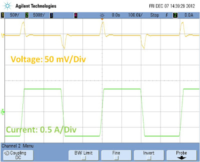
In this setup the power supply operates as a fixed, static voltage source. The power supply’s output voltage is set to the combined total of the full voltage needed to drive the HBLED array at full current plus the minimum voltage needed for the electronic load. The minimum voltage required for the electronic load is when it conducting maximum current and most of the power supply voltage is then applied across the HBLED array. The electronic load’s required minimum voltage is that which supports its operation in its linear range and maintains full dynamic response characteristics. In the case of Keysight electronic loads this minimum voltage for linear dynamic operation is 3 volts.  Conversely the maximum voltage required for the electronic load is when it drops down to minimum current level, where the power supply’s voltage is instead now being dropped across the electronic load instead of the HBLED array. Note that the electronic load may need to maintain a very small amount of bleed current to maintain linear operation in order to provide truly fast rise and fall times. In this way the electronic load is able to regulate the current across the full range with excellent dynamic response. This can be seen in Figure 2 where we were able to achieve approximately 15 microsecond rise time right from the start.


Figure 2: Pulsed current rise time in HBLED array

One advantage of this setup is the wide range of voltage and power that can be furnished to the DUT using a relatively low power electronic load. A common characteristic of electronic loads is that they can dissipate a given amount of power over an extended range of current and voltage. When the electronic load is at maximum current it is at minimum voltage. Conversely when it is near or at zero current it is then at its maximum voltage. In both cases there is only a small amount of power that the electronic load needs to dissipate. For an HBLED array it does not conduct a lot of current until it reaches about 75% of its full operating voltage. As a result the electronic load does not see a lot of power even on a transient basis. For this particular situation we chose to use the Keysight N3303A 240V, 10A, 250W electronic load. This gave a wide range of voltage, current, and power for testing a comparably wide range of different HBLED array assemblies.

So next time you need to source fast, high-power current pulses, you may want to think “load” instead of “source”!


Wednesday, January 7, 2015

A new current measurement methodology: It’s all about counting the electrons going by!

One thing near and dear to us here at the Power and Energy Division is making accurate current measurements. What exactly is current? It’s basically the flow of electric charge per unit of time. In a conductor it’s the flow of electrons through it per unit of time. 

The ampere is the fundamental unit of current in coulombs per second, which equates to 6.241x10¹⁸ electrons per second. Accurate current measurement is one of the core values of virtually all of our products. Some of the precision SMU products can measure down to femtoamp (fA) levels (10-15 amps). This is where we tend to muse that we’re getting down to the levels where we’re virtually counting the individual electrons going by.

While there are a few different ways of measuring current, by far the most common is to measure the voltage drop across a resistive shunt. With careful design this provides the most accurate means of current measurement. There are a lot of non-obvious factors that can introduce unexpected errors that many are not aware of, leading them to believe they have better accuracy than what it really is. A good discussion of what it takes to truly make accurate current measurements was covered in a previous posting “How to make more accurate current measurements”(click here to review). We go through great pains in addressing these things in our products in order to provide accurate and repeatable measurements.

Unlike the volt and the ohm, which have quantum standards for their electrical units, the ampere instead relies on the standards for the volt and ohm for measurement, as a quantum standard for the ampere that directly relates it back to charge is still lacking. However, that may change in the not too distant future. A group of scientists were awarded the Helmholtz Prize in metrology for realization of the measurement of the ampere based on fundamental constants. Basically they’ve created an electron charge pump that moves a small, fixed quantity of electrons under control by a clock. You can say they’re literally “counting the electrons as they go by”. This could become the new SI standard reference for current measurement. To me this is very fascinating to find out about. More can be learned on this from the following link to the press release “Helmholtz Prize for the “new” ampere”(click here to review).  I am curious to see how this all plays out in the long run. Maybe it will lead to yet another, and better, way to make more accurate current measurements in products we all use today in our work in electronics!

Tuesday, January 8, 2013

The difference between constant current and current limit in DC power supplies


Constant Voltage/Constant Current (CC/CV) Power Supplies
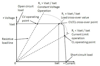
In most of our discussions in “Watt’s Up?” on current limiting we have primarily talked about power supplies as having a constant current (CC) output characteristic. This is what is found in many lab and industrial system power supplies, including most of the power supplies provided by us. Even though the terms often get used interchangeably, there is actually a distinction between constant current and current limit. To help explain this distinction, Figure 1 illustrates the output characteristics of a constant voltage/constant current (CV/CC) power supply.


Figure 1: Operating locus of a CC/CV power supply

Five operating points are depicted in Figure 1:
  1. With no load (i.e. infinite load resistance): Iout = 0 and Vout = Vset
  2. With a load resistance of RL > Vset/Iset: Iout = Vset/RL and Vout = Vset
  3. With a load resistance of RL = Vset/Iset: Iout = Iset and Vout = Vset
  4. With a load resistance of RL < Vset/Iset: Iout = Iset and Vout = Iset*RL
  5. With a short circuit (i.e. zero load resistance): Iout = Iset and Vout = 0


The advantage of a CV/CC power supply is it can be used as either a voltage source or a current source, providing reasonable performance in either mode. The point at which RL = Vset/Iset is the mode crossover point where the power supply transitions between CV and CC operation. For a CV/CC power supply there is a sharp transition between CV and CC operation. Note that for an ideal CV/CC power supply the CV slope is zero (horizontal), indicating zero output resistance for CV operation while the CC slope is infinite (vertical), indicating infinite output resistance for CC operation. Note that this is at DC. How close the slope of each mode is to ideal is what determines quality of load regulation for each.  To achieve good performance for both CV and CC modes requires carefully designed and more complex control loops for each mode. More details about using a power supply as a current source is provided in an earlier posting here, entitled: “Can a standard DC power supply be used as a current source?”

Constant Voltage/Current Limiting Power Supplies
In comparison a constant voltage/current limiting (CV/CL) power supplies are intended to be used only as a voltage source while providing over-current protection for the DUT, as well as protection for the power supply itself. Figure 2 depicts typical output characteristics of a CV/CL power supply.


Figure 2: Operating locus of a CV/CL power supply

In CV/CL power supplies the current limit may be a fixed maximum value or it may be settable. In comparison to Figure 1 CV operation is still the same. However, what is found at the current limit cross-over point there is loss of voltage regulation where the voltage starts falling off. Unlike true CC operation in a CV/CC power supply, CL operation does not typically have as sharply a defined cross-over point and once in CL it may not be tightly regulated between the cross-over and short circuit points. The reason for this is CL control circuits are usually more basic in nature in comparison to a true CC control loop. CL is meant for over-current protection only, not CC operation.  For this reason the correct use of CL is to set its value a bit higher than the maximum current required by the DUT. This assures good voltage regulation for the full range of normal loading. You may find many of the more basic bench power supplies have CV/CL operation and may not be useful as current sources as a result.

Reference: Agilent Technologies DC Power Supply Handbook, application note AN-90B, part number 5952-4020

Monday, December 10, 2012

More on power supply current source-to-sink crossover characteristics


On my earlier posting “Power supply current source-to-sink crossover characteristics” I showed what the effects on the output voltage of a unipolar two-quadrant-power supply were, resulting from the output current on the power supply transitioning between sourcing and sinking. In that example scenario, the power supply was maintaining a constant output voltage and the transitioning between sourcing and sinking current was dictated by the external device connected to and being powered by the power supply. This is perhaps the most common scenario one will encounter that will drive the power supply between sourcing current and sinking current.

Other scenarios do exist that will drive a unipolar two-quadrant power supply to transition between sourcing and sinking output current. One scenario is nearly identical to the earlier posting. However, instead of the device transitioning its voltage between being less and greater than the power supply powering it, the power supply instead transitions its voltage between being less and greater than the active device being normally powered.  A set up for evaluating this scenario on an Agilent N6781A two-quadrant DC source is depicted in Figure 1.


Figure 1: Evaluating current source-to-sink crossover on an N6781A operating in constant voltage

In this scenario having the DC source operating as a voltage source and transitioning between 1.5 and 4.5 volts causes the current to transition between -0.75 and +0.75A.  The voltage and current waveforms captured on an oscilloscope are shown in Figure 2.


Figure 2: Voltage and current waveforms for the set up in Figure 1

The waveforms in Figure 2 are as what should be expected. The actual transition points are where the current waveform passes through zero on the rising and falling edge. An expanded view to the current source-to-sink transition is shown in Figure 3.


Figure 3: Expanded voltage and current waveforms for the set up in Figure 1

As can be seen the voltage ramp transitions smoothly at the threshold point, or zero crossing point, of the current waveform. The reason being is that the DC is maintaining its operation as a voltage source. Its voltage feedback loop is always in control.


Yet one more scenario that will drive a unipolar two-quadrant source to transition between sourcing and sinking current is operate it as a current source and program is current setting between positive and negative values. In this case the device under test that was used is a voltage source.  One real-world example is cycling a rechargeable battery by alternately applying charging and discharging currents to it. The set up for evaluating this scenario, again using an N6781A two-quadrant DC source is depicted in Figure 4.


Figure 4: Evaluating current source-to-sink crossover on an N6781A operating in constant current

For Figure 4 the N6781A was set to operate in constant current and programmed to alternately transition between -0.75A and +0.75A current settings. The resulting voltage and current waveforms are shown in Figure 5.


Figure 5: Voltage and current waveforms for the set up in Figure 4

The waveforms in Figure 5 are as what should be expected. The actual transition points are where the current waveform passes through zero on the rising and falling edge. An expanded view to the current source-to-sink transition is shown in Figure 6.


Figure 6: Expanded voltage and current waveforms for the set up in Figure 4

As the N6781A is operating in current priority the interest is in how well it controls its current while transitioning through the zero-crossing point. As observed in Figure 6 it transitions smoothly through the zero-crossing point. The voltage performance is determined by the DUT, not the N6781A, as the N6781A is operating in constant current.

So what was found here is, for a unipolar two-quadrant DC source, transitioning between sourcing and sinking current should generally be virtually seamless as, under normal circumstances, should remain in either constant voltage or constant current during the entire transition.

Tuesday, August 7, 2012

How Does an Electronic Load Regulate It’s Input Voltage, Current, and Resistance?


In a sense electronic loads are the antithesis of power supplies, i.e. they sink or absorb power while power supplies source power. In another sense they are very similar in the way they regulate constant voltage (CV) or constant current (CC). When used to load a DUT, which inevitably is some form of power source, conventional practice is to use CC loading for devices that are by nature voltage sources and conversely use CV loading for devices that are by nature current sources. However most all electronic loads also feature constant resistance (CR) operation as well. Many real-world loads are resistive by nature and hence it is often useful to test power sources meant to drive such devices with an electronic load operating in CR mode.

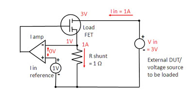
To understand how CC and CV modes work in an electronic load it is useful to first review a previous posting I wrote here, entitled “How Does a Power Supply Regulate It’s Output Voltage and Current?”. Again, the CC and CV modes are very similar in operation for both a power supply and an electronic load. An electronic load CC mode operation is depicted in Figure 1.


Figure 1: Electronic load circuit, constant current (CC) operation

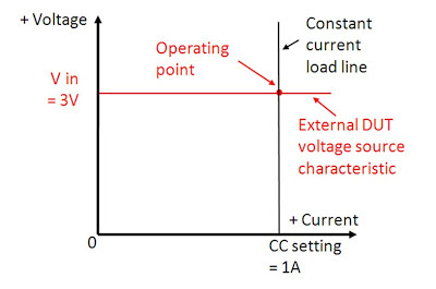
The load, operating in CC mode, is loading the output of an external voltage source. The current amplifier is regulating the electronic load’s input current by comparing the voltage on the current shunt against a reference voltage, which in turn is regulating how hard to turn on the load FET. The corresponding I-V diagram for this CC mode operation is shown in Figure 2. The operating point is where the output voltage characteristic of the DUT voltage source characteristic intersects the input constant current load line of the electronic load.


Figure 2: Electronic load I-V diagram, constant current (CC) operation

CV mode is very similar to CC mode operation, as depicted in Figure 3.  However, instead of monitoring the input current with a shunt voltage, a voltage control amplifier compares the load’s input voltage, usually through a voltage divider, against a reference voltage. When the input voltage signal reaches the reference voltage value the voltage amplifier turns the load FET on as much as needed to clamp the voltage to the set level.


Figure 3: Electronic load circuit, constant voltage (CV) operation

A battery being charged is a real-world example of a CV load, charged typically by a constant current source. The corresponding I-V diagram for CV mode operation is depicted in figure 4.


Figure 4: Electronic load I-V diagram, constant voltage (CV) operation

But how does an electronic load’s CR mode work? This requires yet another configuration, as depicted in figure 5. While CC and CV modes compare current and voltage against a reference value, in CR mode the control amplifier compares the input voltage against the input current so that one is the ratio of the other, now regulating the input at a constant resistance value.  With current sensing at 1 V/A and voltage sensing at 0.2 V/V, the electronic load’s resulting  input resistance value is 5 ohms for its CR mode operation in Figure 5.


Figure 5: Electronic load circuit, constant resistance (CR) operation

An electronic load’s CR mode is well suited for loading a power source that is either a voltage or current source by nature. The corresponding I-V diagram for this CR mode for loading a voltage source is shown in Figure 6. Here the operating point is where the output voltage characteristic of the DUT voltage source intersects the input constant resistance characteristic of the load.


Figure 6: Electronic load I-V diagram, constant resistance (CR) operation

As we have seen here an electronic load is very similar in operation to a power supply in the way it regulates to maintain constant voltage or constant current at its input.  However many real-world loads exhibit other characteristics, with resistive being most prevalent. As a result most all electronic loads are alternately able to regulate their input to maintain a constant resistance value, in addition to constant voltage and constant current.

Monday, July 23, 2012

Why Does My Power Supply Overshoot at Current Limit? Insights on Mode Crossover


One often encountered issue with power supply use is expecting that the current limit will clamp the current to no greater than the set value, only to discover the current initially overshoots when the DUT demands current in excess of the set limit. In some cases the short surge of excess current may be enough to damage a sensitive DUT. Those experienced with power supplies will recognize this as a dynamic characteristic of mode crossover.

What is mode crossover? Mode crossover is the transition point between Constant Voltage (CV) and Constant Current (CC) modes. The dynamic response characteristic of mode crossover is an aspect that separates real-world from ideal-world power supplies. To start it will be helpful to review a previous posting on “How Does a Power Supply regulate its Output Voltage and Current?” Here it is shown there are two control loops in most power supplies, one for regulating the voltage and one for regulating the current. Only one is in control at any given time while the other is “open loop”. The error amplifier that is open loop is up against it stops. When load conditions change such that the power supply transitions through mode crossover the open loop error amplifier needs to recover and gain control of the output. In the more common case of the power supply operating as a voltage source there can be a current overshoot during the brief moment when the load increases beyond the power supply’s current limit setting. Conversely, for a current source, there can be a voltage overshoot during the brief moment when the load decreases, causing the output voltage to rise to the voltage limit setting.

The magnitude of the overshoot depends on many factors relating to both the power supply and the DUT. Supplementary circuitry usually surrounds the error amplifiers to clamp them from being driven into saturation or cutoff so that they can more quickly recover when needed. Amplifiers are carefully selected for their recovery characteristics. Careful design is required to assure a stable transition between modes during crossover while at the same time minimizing the delay and overshoot.  The magnitude of the overshoot also depends on how quickly and to what extent the DUT transitions between loading conditions.

Figure 1 shows the mode crossover current overshoot of a 50 volt, 3 amp general purpose power supply, set for 10 volts and 1 amp output.  The loading DUT is an electronic load set to transition from no load to 10 amps with a slew of 0.8 amps per microsecond. This loading represented a worst case for all practical purposes. When the load transitions to full (i.e. overload) it takes about 6 milliseconds for the current limit control loop to fully take over and bring the current down. During this mode crossover period the current overshoot plateaus at 5 amps, which is the gross current limit capacity of the power supply. Basically this is the point where the power supply runs out of drive.


Figure 1: Constant voltage to constant current mode crossover for 10 V, 1A power supply settings

In Figure 2 the power supply current limit was reduced to 0.1 amps and the mode crossover was again captured. This had an interesting impact on the current overshoot. While the peak current still hit a plateau of 5 amps, the duration of the overshoot was considerably reduced to about 0.5 milliseconds.  The reason for this is there was a much larger difference driving the error amplifier’s input, causing it to transition more quickly. The peak level remained unchanged as it is determined by the power supply’s gross current limit capacity, which is fixed.


Figure 2: Constant voltage to constant current mode crossover for 10 V, 0.1A power supply settings

The extent of an overshoot during mode crossover depends on the power supply as well as the DUT. A power supply optimized for voltage sourcing usually has very little voltage overshoot at mode crossover, but then can have significant current overshoot, as we see here. Conversely, a power supply optimized for current sourcing usually has very little current overshoot at mode crossover, but then can have significant voltage overshoot. Higher performance power supplies may provide faster and better mode crossover performance, but this usually comes at greater expense. Some useful things to do include:
·         Be aware that overshoot during mode crossover is a reality that exists in most all power supplies
·         Try not to oversize the power supply. Be aware that the peak level of voltage or current during mode crossover may be governed more by the maximum voltage and current ratings of the power supply and less by the settings. Using an oversized power supply with its limit set to 5% of its capacity will likely yield a much larger overshoot than a smaller one with it limit set to 50% of its capacity.
·         Understand the nature of your DUT, behavior or fault modes that may cause it to draw an overload, and how sensitive it is to an overload
·         If your DUT is sensitive to an overload, include evaluating the response characteristics of mode crossover as part of your evaluation, using realistic conditions that reflect the characteristics of your DUT.

Recognizing that there is dynamic response characteristics associated with mode crossover of “real-world” power supplies, and they need to be considered, may save a lot of surprise and frustration later on!

Tuesday, July 17, 2012

How Does a Power Supply regulate It’s Output Voltage and Current?


We have talked about Constant Voltage (CV) and Constant Current (CC) power supply operation in many various ways and applications here on the “Watt’s Up?” blog in the past. Indeed, CV and CC are fundamental operating modes of most all power supplies. But what exactly takes place inside the power supply that endows it with the ability to regulate either its output voltage or current, depending on the load? If you ever wondered about this, wonder no longer!

Most all power supplies regulate either their output voltage or output current at a constant level, depending on the load resistance relative to the power supply’s output voltage and current settings. This can be summarized as follows:

·         If R load > (V out / I out) then power supply is in CV mode
·         If R load < (V out / I out) then power supply is in CC mode

To accomplish this most all power supplies have separate voltage and current feedback control loops to limit either the output voltage or current, depending on the load. To illustrate this Figure 1 shows a circuit diagram of a basic 5 volt, 1 amp output series regulated power supply operating in CV mode.


Figure 1: Basic DC Power Supply Circuit, Constant Voltage (CV) Operation

The CV and CC control loops/amplifiers each have a reference input value. In this case the reference values are both 1 volt. In order to regulate output voltage the CV error amplifier compares its 1 volt reference against a resistor divider that divides the output voltage down by a factor of 5, limiting the output voltage to 5 volts. Likewise the CC error amplifier compares its 1 volt reference against a 1 ohm current shunt resistor located in the output current path, limiting the output current to 1 amp. For Figure 1 the load resistance is 10 ohms. Because this load resistance is greater than (V out / I out) = 5 ohms, the power supply is operating in CV mode. The CV error amplifier takes control of the series pass transistor by drawing away excess base current from the series pass transistor, though the diode “OR” network. The CV amplifier is operating in closed loop, maintaining its error voltage at zero volts. In comparison, because the actual output current is only 0.5 amps the CC amplifier tries to turn the current on harder but cannot because the CV amplifier has control of the output. The CC amplifier is operating open loop. Its output goes up to its positive limit while it has -0.5 volts of error voltage. The output I-V diagram for this Constant Voltage operation is shown in Figure 2.


Figure 2: Power Supply I-V Diagram, CV Operation

Now say we increase the load by lowering the output load resistance from 10 ohms down to 3 ohms. Figure 3 shows the circuit diagram of our basic 5 volt, 1 amp output series regulated power supply revised for operating in CC mode with a 3 ohm load resistor.


Figure 3: Basic DC Power Supply Circuit, Constant Current (CC) Operation

Because the load resistor is lower than (V out / I out) = 5 ohms, the power supply switches to CC mode. The CC error amplifier takes control when the voltage drop on the current shunt resistor increases to match the 1 volt reference value, corresponding to 1 amp output, drawing excess base current from the series pass transistor though the diode “OR” network. The CC amplifier is now operating closed loop, regulating the output current to maintain its input error voltage at zero. In comparison, because the actual output voltage is now only 3 volts the CV amplifier tries to increase the output voltage but cannot because the CC amplifier has control of the output. The CV amplifier is operating open loop. Its output now goes up to its positive limit while it has -0.4 volts of error voltage. The output I-V diagram for this Constant Current operation is shown in Figure 4.


Figure 4: Power Supply I-V Diagram, CC Operation

As we have seen most all power supplies have separate current and voltage control loops to regulate their outputs in either a Constant Voltage (CV) or in a Constant Current (CC) mode. One or the other takes control, depending on that the load resistance is in relation to what the power supply’s output voltage and current settings are. In this way both the load and power supply are protected by limiting the voltage and current that is delivered by the power supply to the load. By understanding this theory behind a power supply’s CV and CC operation it is also easier to understand the underlying reason for why various power supply characteristics are the way they are, as well as see how other power supply capabilities can be created by building on top of this foundation. Stay tuned!

Friday, April 27, 2012

Can a standard DC power supply be used as a current source?

The quick answer to this question is, yes, most standard DC power supplies can be used as current sources. However, this question deserves more attention, so what follows is the longer answer.

Most DC power supplies can operate in constant voltage (CV) or constant current (CC) mode. CV mode means the power supply is regulating the output voltage and the output current is determined by the load connected across the output terminals. CC mode means the power supply is regulating the output current and the output voltage is determined by the load connected across the output terminals. When operating in CC mode, the power supply is acting like a current source. So any power supply that can operate in CC mode can be used as a current source (click here for more info about CV/CC operation).

Is a standard power supply a good current source?
An ideal current source would have infinite output impedance (an ideal voltage source would have zero output impedance). No power supply has infinite output impedance (or zero output impedance) regardless of the mode in which it is operating. In fact, most power supply designs are optimized for CV mode since most power supply applications require a constant voltage. The optimization includes putting an output capacitor across the output terminals of the power supply to help lower output voltage noise and also to lower the output impedance with frequency. So the effectiveness of a standard power supply as a current source will depend on your needs with frequency.

At DC, a power supply in CC mode does make a good current source. Typical CC load regulation specifications support this notion (click here for more info about load regulation). For example, an Agilent N6752A power supply (maximum ratings of 50 V, 10 A, 100 W) has a CC load regulation specification of 2 mA. This means that the output current will change by less than 2 mA for any load voltage change. So when operating in CC mode, a 50 V output load change will produce a current change of less than 2 mA. If we take the delta V over worst case delta I, we have 50 V / 2 mA = 25 kΩ. This means that the DC output impedance will always be 25 kΩ or more for this power supply. In fact, the current will likely change much less than 2 mA with a 50 V load change making the DC output impedance in CC mode much greater than 25 kΩ.

Of course, a power supply’s effectiveness as a current source should be judged by the output impedance beyond the DC impedance. See the figure below for a graph of the N6752A CC output impedance with frequency:
If the graph continued in the low frequency direction, the output impedance would continue to rise as a “good” current source should. At higher frequencies, the CC loop gain inside the product begins to fall. As the loop gain moves through unity and beyond, the output capacitor in the supply dominates the behavior of the output impedance, so at high frequencies, the output impedance is lower. So how good the power supply is as a current source depends on your needs with frequency. The higher the output impedance, the better the current source. The output impedance also correlates to the CC transient response (and to a much lesser extent, the output programming response time).

The bottom line here is that in most applications, a standard DC power supply can be used in CC mode as a current source.