Showing posts with label Misc.. Show all posts

Wednesday, September 2, 2015

Yet another new Keysight power product family - this time, compact bench-top DC power!

Last week, I posted about our new photovoltaic (PV) array simulators, models N8937APV and N8957APV. These power supplies can produce an I-V curve as their output characteristic and provide up to 15 kW, 1500 V, and 30 A. Today, I am posting about yet another new series of Keysight power products (wow, our R&D team has been busy!). This new family is at the opposite end of the power spectrum compared to the 15 kW PV array simulators. The new family consists of five models in the 30 to 40 W range with voltages up to 100 V and currents up to 5 A all providing a standard rectangular output characteristic. Click here for the press release that just went out yesterday!

I really like this new family of power supplies and I think you will too!

Why?

Because….

You can choose from a variety of voltage and current combinations to meet your needs.

You can save space on your bench with these very compact models that are only 2U high and ¼-rack-width wide.

You can set and read back very accurate voltage and current values with a basic accuracy of 0.05%.

You can view the high visibility OLED display from nearly any angle.

You can regulate your set voltage at your load to make up for voltage drop in your load leads with remote sense terminals and leads.

You can communicate with these power supplies with either LAN or USB since both interfaces are included.

You can protect your device under test with the built in overvoltage protection and overcurrent protection.

And you can easily access all of the other beneficial features in this tiny package with the on-screen menu system.

So you can see that there is a lot you can do with these compact power packages!

Here is a listing of the models:
Below is a picture of the family showing each of the five new models.
So the next time you have to equip your bench with DC power that goes beyond a basic power supply, consider the new E36100 Series Programmable DC Power Supplies from Keysight Technologies. I know I would (but then again…..look where I work…..)!

Monday, August 31, 2015

Forums and Programming Examples

Hi everybody!

I am not sure how many of you know but we have instrument specific forums at Keysight.  You can find the power supply forums at: Keysight Power Supply Forums.  If you have questions on power supplies you can post them there and either someone here will answer them or sometimes another user has had a similar experience.

We are also in the midst of revamping our example programs to make them more useful for our customers and would like feedback.  We are interested in the following pieces of information:

1. What programming languages/IO Libraries do you use? We are thinking of concentrating on VB.NET, C#, C/C++, Labview, Matlab, Excel (VBA), and Python. Are we missing anything? 

2. Any specific programming examples that would help you more effectively program your power supplies. I cannot guarantee that we will do them but anything requested will be considered. 


You can either answer these questions in the comments here or you could use the forums to respond to the thread that I just created for this blog post: Power Supply Programming Example Feedback Thread.

Thanks!


Friday, August 28, 2015

Verify inverter MPPT algorithms with Keysight’s new PV array simulators

While I normally avoid simply promoting new products in my blog posts, when Keysight Technologies announces a new power product, I feel obligated to mention it here. After all, this is Keysight’s power blog!

So, yesterday, Keysight Technologies announced two new photovoltaic array simulators. Click here for the press release.

The two new models are the N8937APV (208 Vac 3-phase input) and N8957APV (400 Vac 3-phase input). Both are autorangers and provide up to 15 kW, 1500 V, and 30 A on their outputs. Autoranging power supplies cover more output voltage and current combinations than power supplies with rectangular output characteristics. Click here for a previous post on autorangers and here for a post on the power supplies on which these two new models are based. These models can be put in parallel to provide a single output of up to 90 kW! They complement the family of Solar Array Simulators (SAS) that have been available from Keysight for decades.

Pictured below is the front panel of the two new photovoltaic array simulator models (15,000 W in a 3 U package):
So what is a photovoltaic array simulator? It is a specialized power supply that has an output characteristic that mimics the output characteristic of a solar panel (or a collection of solar panels known as a solar array). Photovoltaic (PV) simply refers to something that generates electricity when exposed to light so solar panels are PV devices. Solar panels have an output characteristic called an I-V curve that looks something like the solid line shown below. Isc is the short circuit current, Voc is the open circuit voltage, and Imp and Vmp are the current and voltage at the maximum power point.
Solar arrays are made by taking many solar panels and connecting them in series and parallel combinations for more power. When put in series, the total voltage increases. When put in parallel, the total current increases. Solar inverters take the DC output power from a solar array and convert it from DC into AC that can be used to power AC-mains devices (like those that plug in the wall in your home). So manufacturers of solar inverters are interested in testing their inverters and using a PV array simulator helps them. Instead of connecting their inverters to a real solar panel array that operates only when there is sunlight shining on it, they “simulate” the power output of the array with a PV array simulator. This enables them to test the inverter in many different conditions that affect the I-V curve of a solar panel, such as the temperature surrounding the panel, the angle of the sun on the panel, and cloud cover. Inverters must work when solar panels are subjected to all variations of these parameters, and waiting for them to occur with an actual solar array and the sun is not practical.

The inverter manufacturers are very interested in harvesting as much power as possible from the array, so they design their inverter circuitry to include Maximum Power Point Tracking (MPPT) algorithms that ensure their inverters operate at Pmax (the maximum power point) shown on the I-V curve above. The new Keysight photovoltaic array simulators allow engineers to test their MPPT algorithms.

So the next time you see a rooftop of solar panels, or a parking lot covered with them, or a field filled with panels collecting sunlight and converting it into electrical energy, think about the inverter connected to those panels converting the DC into AC for your use….hopefully, the inverter was fully tested with a Keysight SAS or one of these new photovoltaic array simulators!

Thursday, July 30, 2015

How do I use Python (and no installed IO Library) to talk to my instrument?

Hello everybody,

Our newest support engineer and I have decided to learn Python (https://www.python.org/) so that we can generate programming examples.  We are hearing that more and more customers are using Python so we figured that we would get on the front side and learn some Python.  This blog represents my first attempts at doing anything in Python so there are probably better methods to do this but I wanted to get this out since I am pretty excited about it.  

What we are going to do is do use Python with Telnet and LAN to directly send SCPI commands to my instrument.  The major advantage of this is that with this method, you do not need to use an IO Library so you can use it in different operating systems.  Since we are going to be using Telnet with Python, the first thing that we are going to need to do is to make sure we understand how telnet works with our power supplies.  For all my work here, I will be using my N7953A Advanced Power System (APS) because it is on my desk and it is awesome.  The APS uses port 5024 for telnet.  On my PC running Windows 7, I enter the following in my command window:

Figure 1


Once I hit enter, I get our very friendly welcome screen:

Figure 2


Note the text “Welcome to …”, this will be important later.

To send commands or do queries, you just need to enter the SCPI command after the prompt.   The response to the query will automatically appear after you hit "Enter".  Here is how you do a *IDN? Query:

Figure 3


Note that the query response ends with a new line.  This will be important later.  The prompt also re-appears after every interaction.  In the case of the APS, the prompt is the model number ("N7953A>").  On some other instruments , the prompt is "SCPI>".  Either way, you need to know what the prompt is so that you can account for it later.

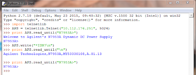
 Now that we are Telnet experts, we are going to switch to Python and send a *IDN? query to my APS.  The first thing we are going to do is to import the telnet library.  After that we are going to create our APS object by opening a telnet session to the instrument (sorry these screenshots might overflow the frame a very tiny bit):

Figure 4


Basically, we are at the same point we are at in Figure 1.  We essentially just hit the "Enter" key.  We need to get to the equivalent to Figure 2 so that we can send a command.  That means that we need to read out all of that welcome text from the power supply.  Luckily, the Python Telnet Library has a read_until function that will read text until it encounters a predefined string.  We know that our prompt to enter text in this case is "N6753A>" so that is what we are going to use:


Figure 5

Let’s send our *IDN? query.  You use the write command to write to the Telnet session.  Helpful tip: all commands sent through telnet need to be terminated with a newline ("\n"):

Figure 6

So now that we sent a query, we need to read the buffer to get the response.  Remember that the query response ends with a newline so we are going to use read_until and use the newline ("\n") as our read_until text:

Figure 7


As you can see we get the same response as before.

So now we sent our command and read the response, we need to read out the prompt again so that our power supply is ready to accept the next command sent to it.  We will just use the same read_until that we used before:

Figure 8


Now we are set to send the next command.

When you are done with programming the instrument, you end the Telnet session with the close command:

Figure 9


So that's an extremely basic example of how to use Python and Telnet.  I used the shell because that is what I used to figure this all out.  You can also write scripts.  As Chris and I learn more about Python, we will be releasing more examples.  Stay tuned for those.


Friday, July 24, 2015

“Adaptive Fast Charging” for faster charging of mobile devices

In some of my previous posts I have talked about USB power delivery 2.0 providing greater power so that mobile devices can be charged up more quickly with their USB adapters.  A key part of this is these devices are incorporating adaptive fast charging systems to accomplish faster charging. So how does this all work anyway?

Let’s first look at the way existing USB charging work, depicted in Figure 1.


Figure 1: Legacy standard USB charging system

When the mobile device is connected to the USB adapter, the mobile device first determines what kind of USB port it is connected to and how much charging current is available that it will be able to draw in order to recharge its battery. The mobile device then proceeds to internally connect its battery up to the USB power through an internal solid state switch that regulates the charging via the device’s internal battery management. However, a major limitation here is the amount of available current and power. Today’s mobile devices are using larger batteries. Up to 4 Ah batteries are commonly used in smart phones and over 9 Ah capacity batteries are being used in tablets. Even with later updates that increased the charging current to 1.5 amps for a dedicated charging port, this is a small fraction of the charging current and power these larger batteries can handle. As one example, a 9 Ah battery having a 1C recommended maximum charging rate equates to a 9 amp charging current. This requires overnight in order to significantly recharge the battery using standard USB charging.

The shortcomings of legacy USB for battery charging purposes has been well recognized and the USB Power Delivery 2.0 specification has been released to increase the amount of power available to as much as 100 watts. This is accomplished by greater voltage, up to 20 volts, and greater current, up to 5 amps. For a mobile device incorporating this, together with an adaptive fast charging system, is able to charge its battery in much less time. This set up is depicted in Figure 2.


Figure 2: USB adaptive fast charging system

With adaptive fast charging, when the mobile device is connected to the USB adapter, after determining that it has compatible fast charging capabilities, it then negotiates for higher voltage and power. After the negotiation the adapter then increases its output accordingly. A key thing here is the mobile device will typically incorporate DC/DC power conversion in its battery management system. Here it will efficiently convert the adapter’s higher voltage charging power into greater charging current at a voltage level comparable to the mobile device’s battery voltage, to achieve much faster charging. Now you will be able to recharge your device over lunch instead of overnight!


Tuesday, June 16, 2015

When is it best to use a battery or a power supply for testing my battery powered device?

As I do quite a bit of work with mobile battery powered devices I regularly post articles here on our “Watt’s Up?” blog about aspects on testing and optimizing battery life for these devices. As a matter of fact my posting from two weeks ago is about the webcast I will be doing this Thursday, June 18th: “Optimizing Battery Run and Charge Times of Today’s Mobile Wireless Devices”. That’s just two days away now!

With battery powered devices there are times it makes sense to use the device’s actual battery when performing testing and evaluation work to validate and gain insights on optimizing performance. In particular you will use the battery when performing a battery run-down test, to validate run-time. Providing you have a suitable test setup you can learn quite a few useful things beyond run-time that will give insights on how to better optimize your device’s performance and run-time. I go into a number of details about this in a previous posting of mine: “Zero-burden ammeter improves battery run-down and charge management testing of battery-powered devices”. If you are performing this kind of work you should find this posting useful.

However, there are other times when it makes sense to use a power supply in place of the device’s battery, to power up the device for the purpose of performing additional types of testing and evaluation work for optimizing the device’s performance. One major factor for this is the power supply can be directly set to specific levels which remain fixed for the desired duration. It eliminates the variability and difficulties of trying to do likewise with a battery, if at all possible. In most all instances it is important that the power supply provides the correct characteristics to properly emulate the battery. This includes:
  • Full two-quadrant operation for sourcing and sinking current and power
  • Programmable series resistance to simulate the battery’s ESR

These characteristics are depicted in the V-I graph in figure 1.


Figure 1: Battery emulator power supply output characteristics

Note that quadrant 1 operation is emulating when the battery is providing power to the device while quadrant 2 is emulating when the battery is being charge by the device.


A colleague here very recently had an article published that goes into a number of excellent reasons why and when it is advantageous to use a power supply in place of trying to use the actual battery, “Simulating a Battery with a Power Supply Reaps Benefits”. I believe you will find this to also be a useful reference.

Wednesday, June 3, 2015

Webcast this June 18th: Optimizing Battery Run and Charge Times of Today’s Mobile Wireless Devices

One thing for certain: Technological progress does not stand still for a moment and there is no place where this is any truer than for mobile wireless devices! Smart phones, tablets, and phablets have all but totally replaced yesterday’s mobile phones and other personal portable devices. They provide virtually unlimited information, connectivity, assistance, and all kinds of other capabilities anywhere and at any time.

However, as a consequence of all these greater capabilities and time spent being actively used is battery run time limitations. Battery run time is one of top dissatifiers of mobile device users. To help offset this manufacturers are incorporating considerably larger capacity batteries to get users through their day. I touched upon this several weeks ago with my earlier posting “Two New Keysight Source Measure Units (SMUs) for Battery Powered Device and Functional Test”. We developed higher power versions of our N678xA series SMUs in support of testing and development of these higher power mobile devices.

Ironically, a consequence of higher capacity batteries leads to worsening of another top user dissatifier, and that is battery charging time. Again, technological progress does not stand still! New specifications define higher power delivery over USB, which can be used to charge these mobile devices in less time. I also touched upon this just a few weeks ago with my posting “Updates to USB provide higher power and faster charging”. The power available over USB will no longer be the limiting factor on how long it takes to recharge a mobile device.

I have been doing a good amount of investigative work on these fronts which has lead me to put together a webcast “Optimizing Battery Run and Charge Times of Today’s Mobile Wireless Devices”. Here I will go into details about operation of these mobile devices during use and charging, and subsequent testing to validate and optimize their performance.  If you do development work on mobile devices, or even have a high level of curiosity, you may want to attend my webinar on June 18. Additional details about the webcast and registration are available at: “Click here for accessing webcast registration”. I hope you can make it!


Friday, May 29, 2015

Should I use RS-232 or GPIB to communicate with my instrument?

Hi everyone,

I am writing this as I am preparing to go to the beach for a week.  My topic today will be short but hopefully useful.    We are going to talk about a subject that has been near and dear to my heart for the past 15 years, serial versus GPIB communication on our instruments.

Back in the days before LAN and USB became instrument standard interfaces, many of our products were designed with RS-232 serial ports in addition to GPIB.  RS-232 is standard on the 681xB AC Source/Analyzers, the E36xxA bench power supplies, the N330xA Electronic loads, as well as a few other products.

RS-232 is an interesting option for communication because it is free, most people have them standard on their computers, and you really only need to buy a reasonably priced cable.  The main drawbacks are the fact that you need to put it in remote mode yourself using the "SYST:REM" command, that reasonably priced cable has to be properly configured, and it is slower than GPIB.  The main drawbacks of GPIB is that it costs more and you need to purchase hardware.

I did some benchmarking this morning using my trusty 6811B AC Source/Analyzer.  I used the proper RS-232 cable and my Keysight 82357B USB to GPIB converter to connect to the 6811B.  I wrote a small program that measures the time to send a "*IDN?" command and receive a response.  The program looped 100 times and calculated the average time.  With GPIB, the average time to send and read back took about 7 ms.  With RS-232, the same send command and read back the response took about 50 ms.

So to answer my titular question, "Should I use RS-232 or GPIB to communicate with my instrument?", my answer in every instance would be to use GPIB.  I know that it is more expensive but you really get what you pay for in this instance.  GPIB is a much faster, more reliable way to communicate with your instruments.

Thanks for reading.  Let us know if you have any questions.

Wednesday, May 20, 2015

Updates to USB provide higher power and faster charging

For those who regularly visit our blog here are already aware I do a fair amount of work with regard to test methodologies for optimizing battery life on mobile wireless devices. One directly related topic I have been actively investigating these past few months is the battery charging aspects for these devices. Recharging the battery on these devices takes a considerable amount of time; typically a couple of hours or longer, and it’s only been getting worse. However, there has been a lot of work, activity, and even new product developments that are making dramatic improvements in recharging your devices’ batteries in less time!

The USB port has become the universal connection for providing charging power for mobile devices. When initially available a USB port could provide up to 500 mA for general power for peripheral devices. It was recognized that this was also a convenient source for charging portable devices but that more current was needed. The USB BC (battery charging) standard was established which formalized charging initially for up to 1.5 amps at 5 volts.

This higher charging current and power was alright for mobile devices of a couple of generations ago, but today’s smart phones, tablets, and phablets are using much larger and higher capacity batteries. The end result is, because USB is 5 volts its power thus limited to 7.5W, that it can take several hours to recharge a device’s battery.  This can be very inconvenient if your battery goes dead during the day!

Simply increasing the USB current is not a total answer as this has limitations. First, the micro USB connectors on mobile devices are rated for no more than about 1.8 to 2 amps. To help on this front there is the new USB Type-C cable and connector specification released last year. The new type-C micro connectors are able to handle up to 3 amps and the standard connectors able to handle up to 5 amps. Higher current alone is not quite enough. Also issued last year was the new USB Power Delivery 2.0 specification. This specifies a system capable of providing up to 20 volts and 5 amps. This is more than order of magnitude improvement in power over the existing USB power. Long charging times due to power limitations will become a thing of the past.

The new USB power delivery voltages and currents are a discrete set of levels as shown in table 1. As can be seen the levels depend on the profile/port designation.


Table 1: USB power delivery 2.0 voltage and current levels

The cables and connectors of course need to be able to handle the given level of current and power.  In review of the standard a lot of work and effort has gone into providing this new capability while maintaining compatibility with the past as well. Thus for a new mobile device to take advantage of these higher power levels, it must be capable of negotiating with the charging power port to furnish it. At the same time, if an earlier generation mobile device is connected, it will only be able to get the default USB 5 volt level.


I’m looking forward to seeing this new USB power delivery put into wide-spread use in various innovative new products. Expect to see more about this topic in future posts from me here!

Monday, March 30, 2015

Big resistors needed for high-power testing

Eighteen months ago, in September of 2013, Keysight (we were Agilent at the time) introduced a new high-power series of power supplies: the N8900 series of 5 kW, 10 kW, and 15 kW autoranging DC power supplies. I posted about those here.

Recently, our environmental lab was doing some testing on one of the 15 kW models that required them to use a low-noise load on the output. They have electronic loads that they can connect to the output to dissipate this level of power, but to be sure they were getting the lowest noise possible, they wanted to use resistors to load the output instead of the electronic loads. Since I was amused by the size of the resistors, I thought I’d capture the moment and share a picture with you.


The picture shows one of our R&D engineers in our environmental lab adjusting the output voltage of a 15 kW N8900 series power supply. Notice that these power supplies pack a lot of power (15 kW) in their small 3 U high package (the white box under the fan). The four big green things on the rack are resistors. The two on the top rack are each rated for 15 kW while the two on the lower rack are each rated for 20 kW. So that’s a total of 70 kW of resistive power! Clearly, these are not your father’s ¼ W resistors!

Even with 70 kW of power dissipation capability, and “only” 15 kW available from our power supply, a big fan was needed to keep the resistors cool…..or perhaps I should say “less hot” since they still get very hot. Of course, with an extra 15 kW of power being dissipated in the room, the room temperature was going up. But that was a good thing since we are still experiencing cold weather here in New Jersey despite the fact that spring started ten days ago. So the extra heat felt good!

Before we came out with the N8900 series of high-power supplies, Matt had posted about some things around his desk that included a 2500 W resistor (click here for his post). At that time, that was a high-power resistor. But now with these 15 kW supplies, you can see we had to go much bigger! And given that these supplies can be paralleled to 100 kW or more….well….I look forward to seeing what our R&D group and environment lab engineers come up with to do resistive load testing on those. Submarine-sized resistors, perhaps? We’ll see….

Tuesday, February 24, 2015

Two New Keysight Source Measure Units (SMUs) for Battery Powered Device and Functional Test

Over the past few years here on “Watt’s Up?” I have posted several articles and application pieces on performing battery drain analysis for optimizing run time on mobile wireless devices. The key product we provide for this application space is the N6781A 20V, +/-3A, 20W source measure module for battery drain analysis. A second related product we offer is the N6782A 20V, +/-3A, 20W source measure module for functional test. The N6782A has a few less key features used for battery drain analysis but is otherwise the same as the N6781A. As a result the N6782A is preferred product for testing many of the components used in mobile devices, where the extra battery drain analysis features are not needed. These products are pictured in Figure 1. While at first glance they may appear the same, one thing to note is the N6781A has an extra connector which is independent voltmeter input. This is used for performing a battery run-down test, one of a number of aspects of performing battery drain analysis. Details on these two SMUs can be found on by clicking on: N6781A product page.  N6782A product page,


Figure 1: Keysight N6781A SMU for battery drain analysis and N6782A for functional test

These products have greatly helped customers through their combination of very high performance specialized sourcing and measurement capabilities tailored for addressing the unique test challenges posed by mobile wireless devices and their components. However, things have continued to evolve (don’t they always!). Today’s mobile devices, like smart phones, tablets and phablets, have an amazing amount of capabilities to address all kinds of applications. However, their power consumption has grown considerably as a result. They are now utilizing much larger batteries to support this greater power consumption in order to maintain reasonably acceptable battery run-time. Optimizing battery life continues to be a critical need when developing these products. With their higher power however, there is in turn a greater need for higher power SMUs to power them during test and development. In response we have just added two new higher power SMUs to this family; the N6785A 20V, +/-8A, 80W source measure module for battery drain analysis and the N6785A 20V, +/-8A, 80W source measure module for functional test. These products are pictured in Figure 2. Details on these two new higher power SMUs can be found on by clicking on: N6785A product page.  N6786A product page.


Figure 2: Keysight N6785A SMU for battery drain analysis and N6786A for functional test

A press release went out about these two new SMUs yesterday; Click here to view. With their greater current and power capability, customers developing and producing these advanced mobile wireless devices and their components now have a way to test them to their fullest, not being encumbered by power limitations of lower power SMUs.

This is exciting to me having been working within the industry for quite some time now, helping customers increase battery life by improving how their devices make more efficient use of the battery’s energy. A key part of this has been by using our existing solutions for battery drain analysis to provide critical insights on how their devices are making use of the battery’s energy.  There is a lot of innovation in the industry to make mobile wireless devices operate with even greater efficiency at these higher power and current levels. There is no other choice if they are going to be successful. Likewise, it is great to see continuing to play a key role in this trend in making it a success!

.

Thursday, January 29, 2015

New Keysight Power Analyzer called IntegraVision

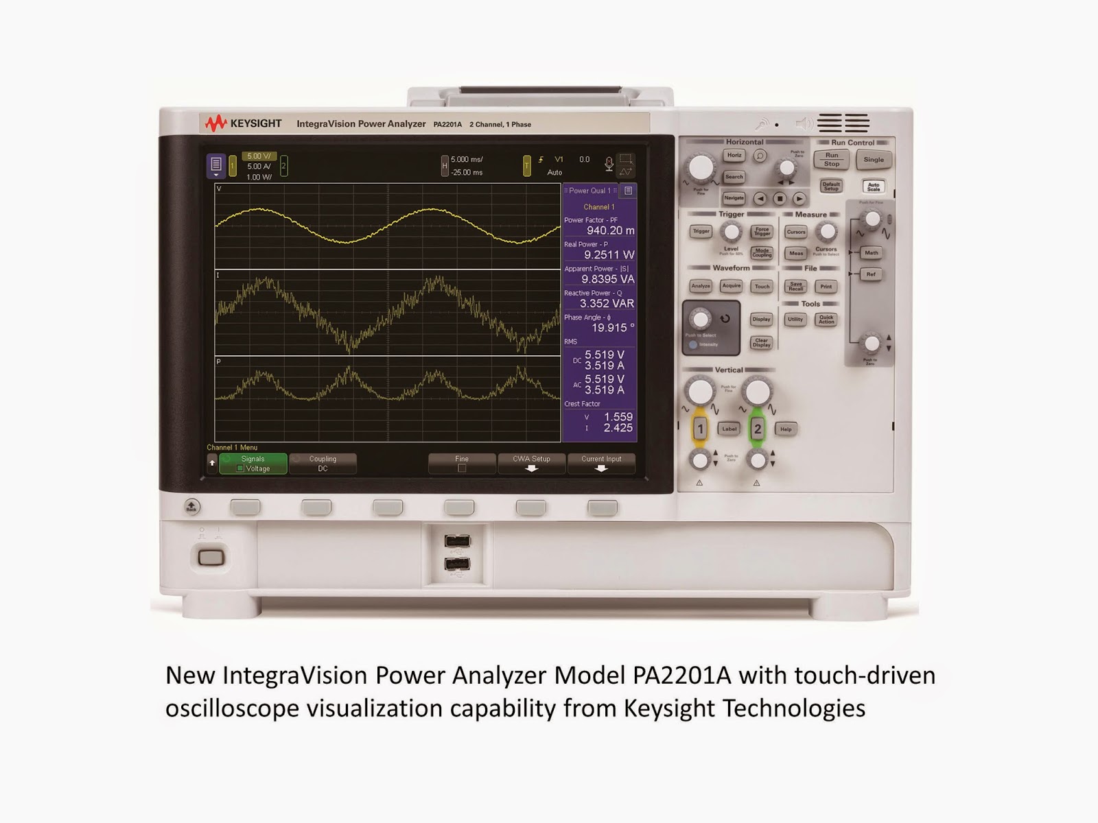
Back on June 23, 2014, I posted about the last Agilent power products to ever be announced. At that time, we had not yet officially changed our name from Agilent to Keysight. So the AC6800 AC sources we released on that date were released under the Agilent name, soon to be rebranded to Keysight. Well, today, I am announcing the first new Keysight power product: the Keysight Technologies IntegraVision Power Analyzer Model PA2201A.


A press release went out about these products earlier today: click here to view. We here at the Power & Energy Division of Keysight have been involved in power products for decades, and of course, Keysight has an oscilloscope division with commensurate experience producing scopes. I consider the new IntegraVision power analyzers to be a combination of the vast experience of our engineers from these two disciplines combining a power analyzer and an oscilloscope. The power analyzer will enable you to accurately measure parameters such as watts, VA, VAR, power factor, crest factor, efficiency, watt-hours, amp-hours, and harmonics while the oscilloscope will allow you to visualize in real time the voltage, current, and power waveforms that are important in your design.

I am very exciting about this new line of power measurement instruments! I have been working for HP/Agilent/Keysight for nearly 35 years now and have always worked with power products during my career. One of my favorite product families to support has been the older sophisticated 6800 AC Power Source/Analyzers (not to be confused with the newer basic AC6800 series mentioned in the first paragraph above). The older AC sources can produce sine waves, square waves, and arbitrary waveforms (for tests such as cycle dropout tests) as well as measure most of the power analyzer parameters mentioned above since they have a power analyzer built into the AC source. But now the new IntegraVision power analyzer goes well beyond the capabilities of the power measurements built into our AC sources. Adding time-based measurements like watt-hours and amp-hours opens up many more energy measurement application areas for this new product and the visual waveform measurements are a huge benefit when doing things like characterizing AC inrush current or product response to AC line disturbances. I am delighted with the performance of the touch-screen on this product – it will help you gain faster insight into your designs plus it just makes using the product fun! With 0.05% basic accuracy, 5 MSample/second 16-bit digitization, and inputs isolated to 1000 V, the IntegraVision power analyzer really is a superb product for power consumption and power conversion applications. Click here for the IntegraVision web page with links to the individual products.

So the next time you need a power analyzer with great accuracy and you also want to see the power waveforms related to your application, be sure to look at Keysight’s new IntegraVision Power Analyzer Model PA2201A. I’m sure you will not be disappointed! And look here for future posts about some of the interesting applications for this product, such as AC power line disturbance measurements and micro-inverter efficiency measurements. Suggest some of your own power measurements for me to make and I’ll see what I can do for a future post for you!

Wednesday, January 7, 2015

A new current measurement methodology: It’s all about counting the electrons going by!

One thing near and dear to us here at the Power and Energy Division is making accurate current measurements. What exactly is current? It’s basically the flow of electric charge per unit of time. In a conductor it’s the flow of electrons through it per unit of time. 

The ampere is the fundamental unit of current in coulombs per second, which equates to 6.241x10¹⁸ electrons per second. Accurate current measurement is one of the core values of virtually all of our products. Some of the precision SMU products can measure down to femtoamp (fA) levels (10-15 amps). This is where we tend to muse that we’re getting down to the levels where we’re virtually counting the individual electrons going by.

While there are a few different ways of measuring current, by far the most common is to measure the voltage drop across a resistive shunt. With careful design this provides the most accurate means of current measurement. There are a lot of non-obvious factors that can introduce unexpected errors that many are not aware of, leading them to believe they have better accuracy than what it really is. A good discussion of what it takes to truly make accurate current measurements was covered in a previous posting “How to make more accurate current measurements”(click here to review). We go through great pains in addressing these things in our products in order to provide accurate and repeatable measurements.

Unlike the volt and the ohm, which have quantum standards for their electrical units, the ampere instead relies on the standards for the volt and ohm for measurement, as a quantum standard for the ampere that directly relates it back to charge is still lacking. However, that may change in the not too distant future. A group of scientists were awarded the Helmholtz Prize in metrology for realization of the measurement of the ampere based on fundamental constants. Basically they’ve created an electron charge pump that moves a small, fixed quantity of electrons under control by a clock. You can say they’re literally “counting the electrons as they go by”. This could become the new SI standard reference for current measurement. To me this is very fascinating to find out about. More can be learned on this from the following link to the press release “Helmholtz Prize for the “new” ampere”(click here to review).  I am curious to see how this all plays out in the long run. Maybe it will lead to yet another, and better, way to make more accurate current measurements in products we all use today in our work in electronics!

Monday, November 24, 2014

Prewired rack delivers up to 90 kW of single-output DC power

As I have mentioned before, I avoid posting product-only-focused material in this blog since our goal is to educate about power-related items rather than to directly promote Keysight products. But when something new comes out, I like to announcement it here.

A little over a year ago, Keysight (we were Agilent at the time) announced a new power supply family with high-power outputs up to 15 kW per output (see link here). These high-power autoranging DC power supplies with individual outputs up to 1500 V or 510 A can be paralleled for even more power. Paralleling outputs with these supplies is simplified since multiple outputs can be grouped to act as a single output and the current share bus enables multiple outputs to more equally share current. But there are other considerations when paralleling multiple units. Wiring the AC inputs and DC outputs together takes design time and assembly time. Integrating the units together physically in a rack also takes time and effort. Designing the system to ensure the safety of operators is also very important. So Keysight decided to offer a prewired rack to help you overcome the challenges associated with racking high-power supplies.

On November 11, 2014 (less than 2 weeks ago), we announced a prewired rack that combines up to six of the 15 kW N8900 series power supplies for total power up to 90 kW from a single output. You can choose from a variety of DC output combinations with voltages from 80 V to 1500 V and currents from 60 A to 3060 A. That’s a lot of current! The rack’s internal configuration makes the multiple outputs appear as a single output allowing you to communicate with just one power supply through LAN, GPIB, or USB (all standard in the system). Click here for the press release for this new system and here for additional system information.


Perhaps you are working in R&D or manufacturing on EV/HEV, alternative energy (fuel cells, solar, etc.), industrial DC motors, large UPS’s, electroplating, or any of the many other high-power application areas that need DC power up to 90 kW with voltages to 1500 V or currents to 3060 A. If so, and you want to spend your engineering resources on your core competencies instead of racking power supplies together, let Keysight help you with our new N8900 Series Rack System.

Thursday, July 31, 2014

Using an IVI Class Compliant Driver

Hi everybody!

In the past, I have talked about the different driver options that we offer.  One of them is the IVI-COM/IVI-C driver.  IVI actually stands for Interchangeable Virtual Instruments. Today I am going to talk about how you can make that abbreviation true using the fact that our power supply can use the IviDCPwr class.   I have received  a few questions in the past about how to do this and every time I do it, it takes me a while to remember all of the steps.  Posting it here will put it somewhere where people (including me!) can find it easily

To start off you need to download and install the following:
  • The Agilent N6700 IVI-COM/IVI-C  driver from Agilent’s website.  If you get the driver from somewhere else, I am not sure how it will work.
  • NI VISA since you will need NI-MAX
  • IVI Compliance package

Once you have all of this, you are ready to get started.


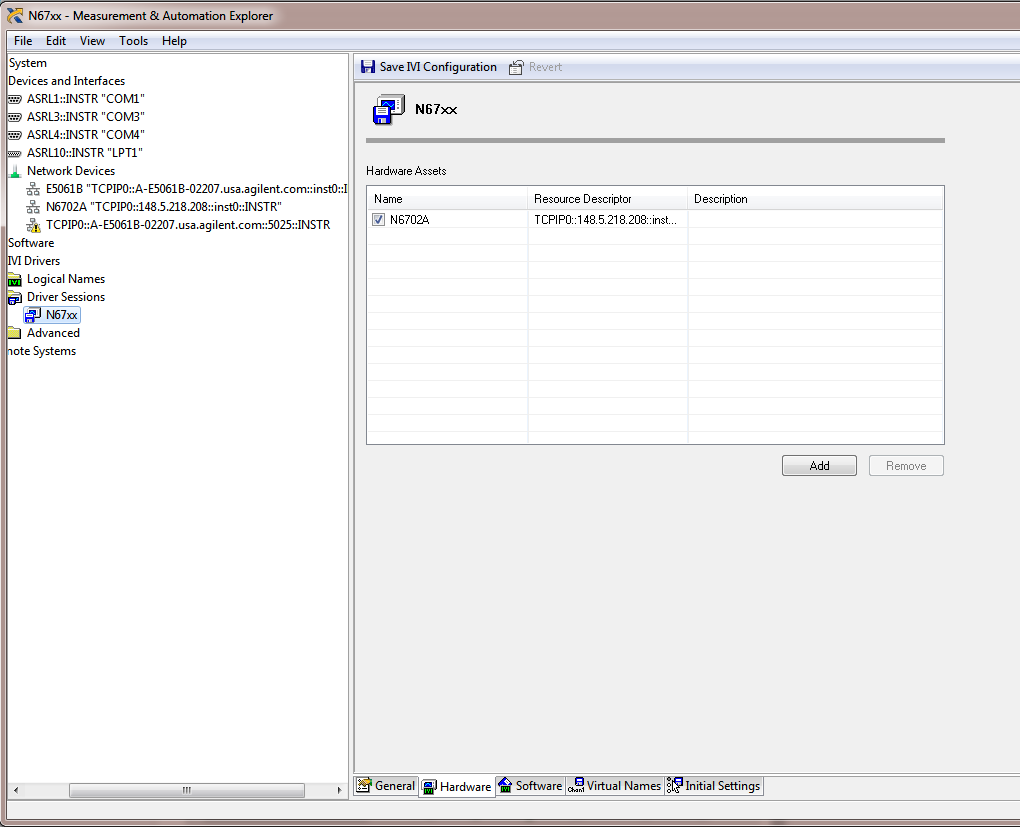
The first thing that you need to do is set your targeted instrument in NI-MAX.  I have a N6702A connected to my LAN.  Here's how it shows up in MAX:


After that, you want to go to the "IVI-Drivers" menu, select the "Driver Sessions" item and right click on it to select "Create new".   From there, click on the "software" tab and select the appropriate driver, in this case the AgN67xx driver.  


You can see here that the driver complies to the IviDcpwr class whcih is what we will be using.  

The next thing to do is in the "Hardware" Tab of the same menu.  You need to specify which instruments use this driver.  Click on "Add" to add your instrument.  It should look like this:


 One thing that I cannot stress enough is that you need to check that checkbox.  In you don't, this will not work and you will spend a little bit of time trying to figure out why you are getting resource not found errors.  Believe me I know this from experience!  After you double check everything make sure that you click on "Save IVI Configuration".

Now choose "Logical Names".  Right click on it and select "Create New".  I created a logical name called "MPS" (this stands for Modular Power System if you were wondering).  You need to refer it to the correct driver session:


Make sure to click on "Save IVI Configuration" again.

With that, you are ready to actually start!  I used Visual C++ 2010 to write my example.  Make sure that you have all of the IVI directories properly entered in your project.  Also make sure that you reference the ividcpwr.lib file in your "linker" settings. 

Here is my program listing:

#include <stdio.h>
#include "IviDCPwr.h"

void main()
{
ViStatus status;
ViSession session;
ViRsrc resource = "MPS";
ViConstString options  = "QueryInstrStatus=true, Simulate=false, DriverSetup= Model=, Trace=false";
ViBoolean idQuery = VI_FALSE;
ViBoolean reset   = VI_TRUE;
ViBoolean enabled = VI_TRUE;
ViChar ChannelName[16] = "";
        ViInt32 index = 2;
        ViInt32 bufferSize = 256;
ViConstString Cname;
ViReal64 Vmeasurement;
ViReal64 Ameasurement;

// This program initializes a session, programs a voltage and current on channel 2, 
// enables the output, and measures voltage and current.

status = IviDCPwr_InitWithOptions(resource, idQuery, reset, options, &session);
status = IviDCPwr_GetChannelName (session,index, bufferSize,ChannelName);

Cname = ChannelName;

status = IviDCPwr_ConfigureOutputEnabled (session,Cname,enabled);
status = IviDCPwr_ConfigureVoltageLevel (session,Cname,4.0);
status = IviDCPwr_ConfigureCurrentLimit(session, Cname, IVIDCPWR_VAL_CURRENT_TRIP, 1);

status = IviDCPwr_Measure (session,Cname,IVIDCPWR_VAL_MEASURE_VOLTAGE,&Vmeasurement);
printf("Measured Voltage on channel is : %f V \n",Vmeasurement);

status = IviDCPwr_Measure (session,Cname,IVIDCPWR_VAL_MEASURE_CURRENT,&Ameasurement);
printf("Measured Current on channel is : %f A \n",Ameasurement);

status = IviDCPwr_close (session);

printf("\n Done - Press Enter to Exit");
getchar();  
}

I am not going to go over the program in detail but here are the key things to note:
  • You need to include "IviDCPwr.h".  All the functions are in there.  You do not need to reference the instrument specific driver.
  • When you initialize the unit, you can refer to it by the name that you define in the "Logical Names" tab above.  In my case, I use "MPS".
  • This is a modular power supply.  The variable "index" is controlling the channel.  
  • I have tested this program and it works properly.
In theory, you should be able to swap this power supply out with another class compliant power supply with minimal programming changes (though in this case if you switch to a single output supply you would need to take out the references to the multiple channels).

One last thing that I want to note is that this will be the last Watt's Up blog posted under the Agilent banner.  Don't worry, we will still be posting the same great content but it will be under a Keysight Technologies banner.  I have been working for Agilent for 14 years now so it will be odd at first to have a new name but I am looking forward to posting many more blogs as a Keysight employee.  Goodbye Agilent Technologies it's been an interesting 14 years!


Monday, June 23, 2014

New Agilent Basic AC Power Sources

I have mentioned several times before that I avoid posting product-only-focused material in this blog, but when we announce something new, it is appropriate for me to mention it here. Today, a press release went out about our new AC sources (click here to view). You may not realize it, but this press release marks the end of an era; these are the last power products Agilent Technologies will ever announce! Now don’t go all non-linear on me…..I’m sure we will continue to design and release new power products for decades to come. But as I mentioned in a previous post (click here), as of August 1, 2014, our products will be Keysight Technologies products and not Agilent Technologies products. So these new AC sources will be rebranded to Keysight in a few weeks, but because we are releasing them before the company name change is official, we have to release them as Agilent and not Keysight. Go figure….

Anyway, what are these new Agilent (soon to be Keysight) AC sources? Well, the model numbers will remain the same through the company name change and they are:

  • AC6801A (500 VA)
  • AC6802A (1000 VA)
  • AC6803A (2000 VA)
  • AC6804A (4000 VA)

This new AC6800 Series of basic AC sources compliments our previous line of more sophisticated AC sources (click here for those) by adding lower cost models and higher power. Here is what the new series looks like (of course, the big one is the 4 kVA model):
All four new AC6800 models share these features:
  • Output capabilities
    • Single-phase output
    • 2 ranges: 0 to 135 Vrms; 0  to 270 Vrms
    • 40 Hz to 500 Hz and DC
    • Sine wave (other waveforms with analog interface)
  • Measurement capabilities
    • Vac, Vdc, Vrms
    • Iac, Idc, Irms, Ipeak, Ipeak&hold, crest factor
    • Watts, VA, VAR, power factor
  • Other
    • Universal AC input
    • LAN (LXI-Core), USB, optional GPIB
    • Optional analog programming interface
The differences in the models are due to the output power ratings and can be summarized by looking at the output characteristics when producing an AC output or a DC output:

For a DC output, the graph above shows only the positive voltage and current quadrant (first quadrant). The output is equally capable of putting out negative voltage and negative current (the third quadrant) and the ratings are the same (except negative). These AC sources only source power; they cannot sink (absorb) power.

These AC sources do have one advanced feature: you can set the phase angle at which the output turns on. Coupled with the ability to measure peak current (and hold the peak current measurement), this is good for AC inrush current measurements.
To view the data sheet, click here.

So that’s the new line of basic AC power sources from Agilent and the last power products to be announced by Agilent. I wonder when the first Keysight power product announcement will be…..wouldn’t you like to know!?!?

Tuesday, June 3, 2014

Upcoming Webinar on High Power Source/Sink Solutions for Testing Bidirectional Energy Devices

Bidirectional and regenerative energy devices both source and sink power and energy. Correspondingly, a solution that can both source and sink power and energy is needed for properly testing them. In the past here on “Watt’s up?” we have talked about what two and four quadrant operation is in our posting “What is bipolar four quadrant power? (Click here to review). We have also talked about cross over behavior between sourcing and sinking current with a DC source that will operate in two quadrants in a two-part posting  “Power supply current source-to-sink crossover characteristics” (Click here to review pt. 1) and (Click here to review pt. 2). These give useful insights about the nature of multi-quadrant solutions for bi-directional test applications.


Figure 1: The four operating quadrants

Bidirectional and regenerative energy devices that are used in many applications, such as satellite power systems, alternative energy, automotive, and many other areas, operate at kilowatt and higher power levels. These higher power levels have a significant impact on solutions and approaches taken to address their testing.  Also, the nature of these bidirectional and regenerative energy devices are not all the same. This also has an impact in that the capabilities of the test solutions need to be different to address these different types of devices.

In my upcoming webinar on June 18th, titled “Conquering the High Power Source/Sink Test Challenge” I will be exploring the test needs of key bidirectional and regenerative energy devices and then go into the details of various test solutions and approaches for sourcing and sinking power and energy, along with their associated advantages and disadvantages. This is just a couple of weeks away. So if you are involved in this kind of work and are interested, or would just like to learn more, you can register online at the following (click here).  In case you cannot join the live event you will still be able to register and listen to seminar afterward instead, as it will be recorded.  I hope you can join in!


.

Wednesday, May 14, 2014

European Space Power Conference (ESPC) for 2014

This week’s blog posting is going in a bit of a different direction, as I likewise did last month, to attend and participate in the 2014 European Space Power Conference (ESPC) for 2014. While this was the tenth ESPC, which I understand takes place every couple of years; this was the first time I had opportunity to attend. One thing for certain; this was all about DC power, which is directly aligned with the things I am always involved in. In this particular instance it was all about DC power for satellites and space-bound crafts and probes.

I initially found it just a bit curious that a number of the keynote speeches also focused a fair amount on terrestrial solar power as well, but I supposed I should not be at all surprised. There has been a large amount of innovation and a variety of things that benefit our daily lives that came out of our own space program, fueled by our involvement in the “space race” and still continuing on to this day. (Can you name a few by chance?). This is a natural progression for a vast number of technological advances we enjoy.

At ESPC there were numerous papers presented on solar cells and arrays, batteries and energy storage, nuclear power sources, power conversion and DC/DC converters, super-capacitors, and a variety of other topics related to power. Just a couple of my learnings and observations include:
·         There was a very high level of collaboration of sharing findings and answering questions among peers attending the event
·         While batteries generally have very limited lives, from findings presented, it was interesting to see how well they have performed over extended periods in space, lasting last well in excess of their planned life expectancies. It is a reflection of a combination of several things including careful control and workmanship, understanding life-shortening and failure mechanisms, how to take properly treat them over time, what should be expected, as well as other factors contributing to their longevity. I expect this kind of work will ultimately find its way to being applied to using lithium ion batteries in automotive as well.
·         A lot of innovation likewise continues with solar cell development with higher conversion efficiencies coming from multi-junction devices. Maybe we’ll see this become commonplace for terrestrial applications before long!
·         A number of research papers were presented from participants from universities as well. In all, the quality of work was excellent.

I was there with another colleague, Carlo Canziani. Together we represented some of our DC power solutions there, including our N7905A DC Power Analyzer, N7900 series Advanced Power System (APS), and E4360A series Solar Array Simulator (SAS) mainframe and modules. These are the kinds of advanced power stimulus and measurement test instruments vital for conducting testing on satellite and spacecraft power components and systems.

In all it was a refreshing change of pace to be at an event where power is the primary focus, and if this happens to be an area of interest to you as well, you can find out more about ESPC from their site by clicking on the following link: (ESPC2014). Maybe you will find it worthwhile to attend or even present results of some of your work at the next one as well!

Wednesday, April 30, 2014

New Software Update for the N7900 Advanced Power System

Hi everybody,

Last year, we introduced the Agilent N7900 Advanced Power System (hereon in shortened to N7900 APS).  The N7900 APS is a full of great features that can only be accessed using the instrument's programming interface.  The programming interface works very well but sometimes you just don't want write and troubleshoot a program, you just want something that works.

Well, I have the chance to share some pretty exciting news.  We want to provide you software that makes some of these great features easy for you to use.  The software is the 14585A Control and Analysis Software.  This software was previously only available for the N6705 DC Power Analyzer.

The 14585A software is a standalone application that unlocks three key features: it allows you to look at a graphical representation of the measured data in Scope Mode, create arbitrary waveforms in Arb mode, and log long term data in datalogger mode.  These three advanced features can be setup and run by adjusting a few settings and pressing a few buttons.

 The software comes with a 30 day free trial so feel free to download it to check it out.  Please note that you need at least version A.01.13 of the APS firmware in order to use the software.

You can find the latest APS firmware at:
APS Firmware

You can find the software at:
14585A Software

If you have any questions on the software, feel free to leave us some comments.  Thanks for reading!

Wednesday, January 8, 2014

Keysight Technologies – What’s in a name, anyway?

This is an exciting time for us! Yesterday, January 7, 2014, we learned what our new company name will be: Keysight Technologies. Here is a link to the official press release: 

If you have not heard by now, back in September of 2013, Agilent Technologies announced it would split into two companies by the end of 2014. Since I started in 1980, 33+ years ago, I have worked for and will continue to work for the electronic measurement side of the business. For my first 19 years with the company, we were Hewlett-Packard, a company that formed in 1939 as a test and measurement company and eventually birthed Silicon Valley. It is this electronic measurement side of the business that is getting the new name, just as we did in 1999 when we became Agilent from Hewlett-Packard. The other part of Agilent, the life sciences, diagnostics, and applied markets side will continue to operate under the Agilent name. Note that the electronic measurement side will still have the same great people designing and supporting the same great products and services….just a new name: Keysight Technologies.

So let’s take a closer look at the new name, logo, and tagline for Agilent’s electronic measurement business:


The name combines the words “key”, meaning essential, and “insight” meaning intuitive perception. Essential intuitive perception. Seeing what others cannot. A key can also be used to unlock something; we will continue to unlock measurement insights, as our tagline says. And we have been doing this for 75 years - since the day that Bill Hewlett and Dave Packard released their first electronic test instrument, an audio oscillator, in 1939. By the way, it is purely a coincidence that the Watt’s Up? authors, Ed, Matt, and I have combined experience of more than 75 years as stated in our blog header, although I’d like to think that the three of us have been unlocking measurement insights in the AC and DC power field for a combined total of 75 years! In fact, we now have a total of more than 80 years’ experience between the three of us and I will update the header later this year when we officially begin using the Keysight name. But I digress...

The logo symbol is derived from one of the most fundamental wave shapes there is: a sine wave – a wave shape from which all other wave shapes can be built. This is very appropriate for our 100% focus on electronic measurement, not to mention a tribute to our original founders, Bill and Dave, for their audio oscillator. And the power products and topics that you read about here in Watt’s Up? are equally represented by the logo symbol, especially our AC sources! If you really think about it, Keysight will be doing what Hewlett-Packard originally set out to do and Agilent continued to do for decades: build the world’s leading test and measurement company.

So what’s in a name? Essential intuitive perception is in our name. A clear focus on electronic measurement is in our name. Our strong and deep heritage is in our name. And when we begin to fully operate as Keysight Technologies later this year, what you will find behind our name will be the same high quality products and people that you have come to know. That’s what’s in the name Keysight Technologies!