Paramount in most any good electronic test system is the
need to adequately protect the device under test (DUT), as well as the test
equipment, from inadvertent damage due to possible faults with the yet-untested
DUT, accidental misconnections, misapplication of power, and a large number of
other unanticipated events that can occur. It is no surprise that a lot of
these unanticipated events by nature are related to the powering of the DUT.
For this reason good system DC power supplies incorporate a number of features
designed to protect both the DUT, as well as the power supply, in the event of
an unanticipated fault occurring. Two
related protection features incorporated into our DC system power supplies are
the remote inhibit and the discrete fault indicator (RI/DFI). These features
provide real-time protection enabling immediate shutting down the power supply,
as well as enabling the power supply to take immediate action, on the event of
detecting the occurrence of an unanticipated event or fault.
The remote inhibit is a digital input control while the
discrete fault indicator is a digital output control signal, incorporated into
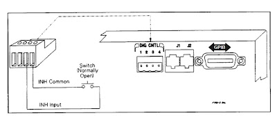
the digital I/O port on our system DC power supplies. An example of a digital
I/O port is illustrated in Figure 1. When the digital I/O port is configured
for fault/inhibit (also called RI/DFI) pins 1 and 2 are the open collector and
emitter of an isolated transistor, to serve as a digital output control, and
pin3 and 4 are the digital input and common for the inhibit control input. The
remote inhibit and the fault indicator can be used independently as well as in
combination, for protecting the DUT.
Figure 1: Multi-function digital I/O port on Agilent
6600A series system DC power supplies
As the name implies, the remote inhibit is a digital
control input, when activated, immediately disables the DC power supply’s
output. One way this is commonly used is to connect an emergency shutdown
switch that can be conveniently activated in the event of a problem. This may
be a large pushbutton, or it may be a switch incorporated into a fixture safety
cover. This arrangement is shown in Figure 2.
Figure 2: Remote inhibit using external switch
The fault indicator (i.e. FLT, FI, or DFI) digital output
signal originates from the system DC power supply’s status system. The status
system is a configurable logic system within the power supply having a number
of registers that keep track of its status for operational, questionable, and
standard events. Many of these events can be logically OR’ed together as needed
to provide a fault output signal when particular, typically unanticipated,
events occurs with the power supply. Items tracked by questionable status group
register, like over voltage and over current, for example, are commonly
selected and used for generating a fault output signal. An overview of the
power supply status register system was discussed by a colleague in a previous
posting. If you are interested in learning more; click here.
The fault indicator output can in turn be used to control
an external activity for protecting the DUT, such as opening a disconnect relay
to isolate the DUT, as one example, as depicted in Figure 3.
Figure 3: Fault output controlling an external disconnect
relay
For DUTs that require multiple bias voltage inputs it is
usually desirable that if a fault is detected on one bias input, that the other
bias inputs are immediately shut down in conjunction with the one detecting a
fault. The fault outputs and remote inhibit inputs on several DC power supplies
can be used in combination by chaining them together, as depicted in Figure 4,
to accomplish this task, to safeguard the DUT.
Figure 4: Chaining fault indicators and remote inhibits
on multiple DC power supplies


Dear Sir:
ReplyDeleteI purchased a HP6622A power supply with options 700 and 750. When I received the power supply, CHANNEL 1, was in a UNR state (unregulated) and would not output the voltage that I had wanted. The CHANNEL is effectively disabled.
I read your posts about fault protections etc., however, there is little or no information about the source of the UNR message. A TEST? query returns no errors.
There is conflicting information about the origin of the UNR but little available information.
Other than this issue the unit appears to be OK. Therefore, if there is a hardware connection that needs to be made in the back of the unit, or some simple pushbutton solution to this problem can you please reply and tell me how to enable CH 1 so that it will be operational? Thanks.
Hello RF Tech,
ReplyDeleteThe “UNR” annunciator on the front panel of your 6622A indicates that the output is unregulated, i.e. neither the constant voltage (CV), nor constant current (CC) control loops are in control of the output. I had actually written a posting here on “Watt’s Up?” about this. The posting is entitled: “What is going on when my power supply displays “UNREG”?” at the following link:
http://powersupplyblog.tm.agilent.com/2012/03/what-is-going-on-when-my-power-supply.html
Do you have the operating manual for your HP6622A? It is available on-line from the Agilent website and you can access it from the following link:
http://cp.literature.agilent.com/litweb/pdf/5957-6377.pdf
Chapter 3, starting on page 31 describes how to operate the unit from its front panel and what all the controls and display functions are. There are references to what UNR is on pages 33 and 46.
All the above assumes the power supply is in working order. Certain loading conditions, usually involving connecting the output to another active power source, can cause UNR. When the output is not connected to anything you should not get UNR. In this event it is possible the output has been damaged somehow, which can also cause it to display UNR as the output is no longer able to go to its output voltage or current setting. In that case the unit may need troubleshooting and service.
If you need to pursue additional help you should contact Agilent at 1-800-829-4444 for support.
Regards,
Ed