Showing posts with label output disable. Show all posts

Friday, December 5, 2014

Why does the response time of OCP vary on the power supply I am using and what can I do about it? Part 2

In the first part of this posting (click here to review) I highlighted what kind of response time is important for effective over current protection of typical DUTs and what the actual response characteristic is for a typical over current protect (OCP) system in a test system DC power supply. For reference I am including the example of OCP response time from the first part again, shown in Figure 1.


Figure 1: Example OCP system response time vs. overdrive level

Here in Figure 1 the response time of the OCP system of a Keysight N7951A 20V, 50A power supply was characterized using the companion 14585A software. It compares response times of 6A and 12A loading when the current limit is set to 5A. Including the programmed OCP delay time of 5 milliseconds it was found that the actual total response time was 7 milliseconds for 12A loading and 113 milliseconds for 6A loading.  As can be seen, for reasons previously explained, the response time clearly depends on the amount of overdrive beyond the current limit setting.

As the time to cause over current damage depends on the amount of current in excess of what the DUT can tolerate, with greater current causing damage more quickly, the slower response at lower overloads is generally not an issue.  If however you are still looking how you might further improve on OCP response speed for more effective protection, there are some things that you can do.

The first thing that can be done is to avoid using a power supply that has a full output current rating that is far greater than what the DUT actually draws. In this way the overdrive from an overload will be a greater percentage of the full output current rating. This will normally cause the current limit circuit to respond more quickly.

A second thing that can be done is to evaluate different models of power supplies to determine how quickly their various current limit circuits and OCP systems respond in based on your desired needs for protecting your DUT. For various reasons different models of power supplies will have different response times. As previously discussed in my first part, the slow response at low levels of overdrive is determined by the response of the current limit circuit.

One more alternative that can provide exceptionally fast response time is to have an OCP system that operates independently of a current limit circuit, much like how an over voltage protect (OVP) system works. Here the output level is simply compared against the protect level and, once exceeded, the power supply output is shut down to provide near-instantaneous protection. The problem here is this is not available on virtually any DC power supplies and would normally require building custom hardware that senses the fault condition and locally disconnects the output of the power supply from the DUT. However, one instance where it is possible to provide this kind of near-instantaneous over current protection is through the programmable signal routing system (i.e. programmable trigger system) in the Keysight N6900A and N7900A Advanced Power System (APS) DC power supplies. Configuring this triggering is illustrated in Figure 2.


Figure 2: Configuring a fast-acting OCP for the N6900A/N7900A Advanced Power System

In Figure 2 the N7909A software utility was used to graphically configure and download a fast-acting OCP level trigger into an N7951A Advanced Power System. Although this trigger is software defined it runs locally within the N7951A’s firmware at hardware speeds. The N7909A SW utility also generates the SCPI command set which can be incorporated into a test program.


Figure 3: Example custom-configured OCP system response time vs. overdrive level

Figure 3 captures the performance of this custom-configured OCP system running within the N7951A. As the OCP threshold and overdrive levels are the same this can be directly compared to the performance shown in Figure 1, using the conventional, current limit based OCP within the N7951A. A 5 millisecond OCP delay was included, as before. However, unlike before, there is now virtually no extra delay due to a current limit control circuit as the custom-configured OCP system is totally independent of it. Also, unlike before, it can now be seen the same fast response is achieved regardless of having just a small amount or a large amount of overdrive.

Because OCP systems rely on being initiated from the current limit control circuit, the OCP response time also includes the current limit response time. For most all over current protection needs this is usually plenty adequate.  If a faster-responding OCP is called for minimizing the size of the power supply and evaluating the performance of the OCP is beneficial. However, an OCP that operates independently of the current limit will ultimately be far faster responding, such as that which can be achieved either with custom hardware or making use of a programmable signal routing and triggering system like that found in the Keysight N6900A and N7900A Advanced Power Systems.

Wednesday, March 20, 2013

Open sense lead detection, additional protection for remote voltage sensing


A higher level of voltage accuracy is usually always needed for powering electronic devices under test (DUTs). Many devices provide guaranteed specifications for operating at minimum, nominal, and maximum voltages, so the voltage needs to accurate as to not require unacceptable amounts of guard banding of the voltage settings.

One very significant factor that affects the accuracy of the voltage at the DUT is the voltage drop in the wiring between the output terminals of the power supply and the actual DUT fixture, due to wiring’s inherent resistance, as shown in Figure 1.


 A standard feature of most all system DC power supplies is remote voltage sensing. Instead of the voltage being regulated at the output terminals of the DC power supply’s output terminal, it is instead sensed and regulated at the DUT itself, compensating for the voltage drop in the wiring. Additional details of this are documented in an earlier posting: “Use remote sense to regulate voltage at your load”

While remote voltage sensing addresses the problem of voltage drop in wiring affecting the voltage accuracy at the DUT, it then raises the concern of what happens if one of the sense lines becomes disconnected. Will the DC power supply voltage climb up to it maximum potential causing my DUT to be damaged?  Although this is a very legitimate concern, often the voltage is usually kept within a reasonable range of the setting by a feature referred to as “open sense lead protection”. A deeper dive on the issue of open sense lines and open sense lead protection are discussed at our posting: “What happens if remote sense leads open?”

Even with open sense lead protection and the voltage being kept within a reasonable range of the setting, this can be a concern for some customers who are relying on a high level of DC voltage accuracy at the DUT for test and calibration purposes. One categorical example of this is battery powered devices, where ADC circuits that need to precisely monitor the battery input voltage have to be accurately calibrated. If the voltage from the DC power supply has significant error, the DUT will be miss-calibrated.

One issue with open sense lead protection is it is a passive protection mechanism. It is simply a back up that takes over when a sense line is open. There is no way of knowing the sense lead is open. No error flag is set or fault condition tripped. The voltage being read back is the same as that is being regulated by the voltage sensing error amplifier, which is the same as the set voltage, so all looks fine from a read-back perspective. This is where open sense lead detection takes over. Open sense lead detection is a system that actively checks to see if the sense lines are doing their job. If not it lets the test system know there is a fault.

Open sense detection is not a common feature for most system DC power supplies. As one example we do employ it in our 663xx series Mobile Communications DC Sources as these are used for powering, testing and calibrating battery powered wireless devices. In the case of an open sense line condition it generates a fault condition and it keeps the output of the DC source powered down. It also provides status information on which of the sense lines are open as well.

Tuesday, March 12, 2013

What is a power supply’s over current protect (OCP) and how does it work?


One feature we include in our Agilent system DC power supplies for providing additional safeguard for overload-sensitive DUTs is over current protect, or OCP. While some may think this is something separate and independent of current limiting, OCP actually works in concert with current limiting.

Current limiting protects overload-sensitive DUTs by limiting the maximum current that can be drawn by the DUT to a safe level. There are actually a variety of current limit schemes, depending on the level of protection required to safeguard the DUT during overload. Often the current limit is relatively constant, but sometimes it is not, depending on what is best suited for the particular DUT. Additional insights on current limits are provided in an earlier posting, entitled “Types of current limits for over-current protection on DC power supplies“.

By limiting the current to a set level may DUTs are adequately protect from too much current and potential damage. When in current limit, if the overload goes away the power supply automatically goes back to constant voltage (CV) operation. However, current limit may not be quite enough for some DUTs that are very sensitive to overloads. This is where OCP works together with the current limit to provide an additional level of protection. With OCP turned on, when the DC power supply enters into current limit OCP takes over after a specified time delay and shuts down the output of the DC power supply. The delay time is programmable. This prevents OCP from shutting down the DC power supply from short current spikes and other acceptably short overloads that are not considered harmful. Like over voltage protect or OVP, after tripping the output needs to be disabled and an Output Protect Clear needs to be exercised in order to reset the power supply so that its output can be re-enabled.  Unlike OVP, OCP can be turned on and off and its default is usually off. In comparison, OVP is usually always enabled and cannot be turned off. A typical OCP event is illustrated in Figure 1.


Figure 1: OCP operation

When powering DUTs, either on the bench or in a production test system, it is always imperative that adequate safeguards are taken to protect both the DUT as well as the test equipment from inadvertent damage. Over current protect or OCP is yet another of many features incorporated in system DC power supplies you can take advantage of to protect overload-sensitive DUTs from damage during test!

Friday, February 8, 2013

Protecting your DUT using a power supply’s remote inhibit and fault indicator features


Paramount in most any good electronic test system is the need to adequately protect the device under test (DUT), as well as the test equipment, from inadvertent damage due to possible faults with the yet-untested DUT, accidental misconnections, misapplication of power, and a large number of other unanticipated events that can occur. It is no surprise that a lot of these unanticipated events by nature are related to the powering of the DUT. For this reason good system DC power supplies incorporate a number of features designed to protect both the DUT, as well as the power supply, in the event of an unanticipated fault occurring.  Two related protection features incorporated into our DC system power supplies are the remote inhibit and the discrete fault indicator (RI/DFI). These features provide real-time protection enabling immediate shutting down the power supply, as well as enabling the power supply to take immediate action, on the event of detecting the occurrence of an unanticipated event or fault.

The remote inhibit is a digital input control while the discrete fault indicator is a digital output control signal, incorporated into the digital I/O port on our system DC power supplies. An example of a digital I/O port is illustrated in Figure 1. When the digital I/O port is configured for fault/inhibit (also called RI/DFI) pins 1 and 2 are the open collector and emitter of an isolated transistor, to serve as a digital output control, and pin3 and 4 are the digital input and common for the inhibit control input. The remote inhibit and the fault indicator can be used independently as well as in combination, for protecting the DUT.


Figure 1: Multi-function digital I/O port on Agilent 6600A series system DC power supplies

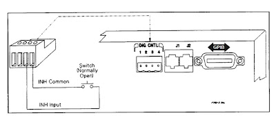
As the name implies, the remote inhibit is a digital control input, when activated, immediately disables the DC power supply’s output. One way this is commonly used is to connect an emergency shutdown switch that can be conveniently activated in the event of a problem. This may be a large pushbutton, or it may be a switch incorporated into a fixture safety cover. This arrangement is shown in Figure 2.


Figure 2: Remote inhibit using external switch

The fault indicator (i.e. FLT, FI, or DFI) digital output signal originates from the system DC power supply’s status system. The status system is a configurable logic system within the power supply having a number of registers that keep track of its status for operational, questionable, and standard events. Many of these events can be logically OR’ed together as needed to provide a fault output signal when particular, typically unanticipated, events occurs with the power supply. Items tracked by questionable status group register, like over voltage and over current, for example, are commonly selected and used for generating a fault output signal. An overview of the power supply status register system was discussed by a colleague in a previous posting. If you are interested in learning more; click here.
The fault indicator output can in turn be used to control an external activity for protecting the DUT, such as opening a disconnect relay to isolate the DUT, as one example, as depicted in Figure 3.


Figure 3: Fault output controlling an external disconnect relay

For DUTs that require multiple bias voltage inputs it is usually desirable that if a fault is detected on one bias input, that the other bias inputs are immediately shut down in conjunction with the one detecting a fault. The fault outputs and remote inhibit inputs on several DC power supplies can be used in combination by chaining them together, as depicted in Figure 4, to accomplish this task, to safeguard the DUT.


Figure 4: Chaining fault indicators and remote inhibits on multiple DC power supplies

The remote inhibit and fault indicator digital control signals on system DC power supplies provide a number of ways to disable power and take other actions for safeguarding the DUT. Their action is immediate, not requiring communication to, and intervention from, the test system controller. At the same time the system DC power supply generates status signals and can issue a service request (SRQ) to the test system controller so that it is notified of a problem condition and take appropriate correction action as well. The remote inhibit and fault indicator digital control signals are just two of many features found in many good system DC power supplies to assure the DUT is always adequately protected during test!