Showing posts with label output disconnect. Show all posts

Friday, May 22, 2015

New performance options for the N6900A Advance Power System gives greater versatility for your test needs

Our N6900 and N7900 series Advanced Power System (APS) DC power supplies are some of our most sophisticated products, setting new levels of performance and capabilities on many fronts. They come in 1kW and 2kW power levels as shown in Figure 1 and can be grouped together to provide much greater power levels as needed.


Figure 1: N6900 and N7900 Advanced Power System 1kW and 2kW models

Most noteworthy is that these can be turned into full two-quadrant DC sources by connecting up the optional 1kW N7909A Power Dissipator (2 needed for 2kW units) providing 100% power sinking capability. This makes APS an excellent solution for battery, battery management and many alternative energy applications, where both sourcing and sinking power are needed.
  • The N6900 series DC power supplies are designed for ATE applications where high test throughput and high performance is critical.
  • The N7900 series dynamic DC power supplies are designed for ATE applications where high speed dynamic sourcing and measurement is needed, in additions to high performance.

A lot more about these products is covered in another post on our General Purpose Electronic Test Equipment (GEPTE) blog when they were first announced. This is a great resource for learning more about APS and can be accessed from the following link: “New Advanced Power System: Designed to Overcome Your Toughest Test Challenges”

If you are a regular visitor to the “Watt’s Up?” blog no doubt you have seen we have shared a lot about how to do things with the N6900 series and N7900 series APS to address a number of difficult test challenges. A lot of times it would have otherwise required additional equipment or custom hardware to accomplish these tasks. While many of these examples are suitable for the N6900 and N7900, a good number of times examples make use of the additional capabilities only available in the N7900 series.

In certain test situations the N6900 series APS would be a great solution and lower cost than the N7900 series, if only it also had a certain additional capability. To this end Keysight has recently announced four new performance options for the N6900 series APS to address a specific test need you may have, as follows:
  1. Accuracy Package (option 301): Adds a second seamless measurement range for current
  2. Measurement Enhancements (Option 302): Adds external data logging and voltage and current digitizers with programmable sample rates
  3. Source and Speed Enhancements (Option 303): Adds constant dwell arbitrary waveforms and output list capability, and faster up and down programming speed
  4. Disconnect and Polarity-Reversal Relays (Option 760 and 761): Provides galvanic isolation and allows output voltage to be switched between positive and negative values

 Additional details about the N6900 series APS and the four new performance options are available from the recent press release, available at the following link: “Keysight Technologies adds Versatile Performance Options to Industry’s Fastest Power Supplies”

With these new options you now have a spectrum of choices in the Advanced Power System product family to better address any test challenges you may be faced with!

Friday, February 8, 2013

Protecting your DUT using a power supply’s remote inhibit and fault indicator features


Paramount in most any good electronic test system is the need to adequately protect the device under test (DUT), as well as the test equipment, from inadvertent damage due to possible faults with the yet-untested DUT, accidental misconnections, misapplication of power, and a large number of other unanticipated events that can occur. It is no surprise that a lot of these unanticipated events by nature are related to the powering of the DUT. For this reason good system DC power supplies incorporate a number of features designed to protect both the DUT, as well as the power supply, in the event of an unanticipated fault occurring.  Two related protection features incorporated into our DC system power supplies are the remote inhibit and the discrete fault indicator (RI/DFI). These features provide real-time protection enabling immediate shutting down the power supply, as well as enabling the power supply to take immediate action, on the event of detecting the occurrence of an unanticipated event or fault.

The remote inhibit is a digital input control while the discrete fault indicator is a digital output control signal, incorporated into the digital I/O port on our system DC power supplies. An example of a digital I/O port is illustrated in Figure 1. When the digital I/O port is configured for fault/inhibit (also called RI/DFI) pins 1 and 2 are the open collector and emitter of an isolated transistor, to serve as a digital output control, and pin3 and 4 are the digital input and common for the inhibit control input. The remote inhibit and the fault indicator can be used independently as well as in combination, for protecting the DUT.


Figure 1: Multi-function digital I/O port on Agilent 6600A series system DC power supplies

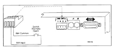
As the name implies, the remote inhibit is a digital control input, when activated, immediately disables the DC power supply’s output. One way this is commonly used is to connect an emergency shutdown switch that can be conveniently activated in the event of a problem. This may be a large pushbutton, or it may be a switch incorporated into a fixture safety cover. This arrangement is shown in Figure 2.


Figure 2: Remote inhibit using external switch

The fault indicator (i.e. FLT, FI, or DFI) digital output signal originates from the system DC power supply’s status system. The status system is a configurable logic system within the power supply having a number of registers that keep track of its status for operational, questionable, and standard events. Many of these events can be logically OR’ed together as needed to provide a fault output signal when particular, typically unanticipated, events occurs with the power supply. Items tracked by questionable status group register, like over voltage and over current, for example, are commonly selected and used for generating a fault output signal. An overview of the power supply status register system was discussed by a colleague in a previous posting. If you are interested in learning more; click here.
The fault indicator output can in turn be used to control an external activity for protecting the DUT, such as opening a disconnect relay to isolate the DUT, as one example, as depicted in Figure 3.


Figure 3: Fault output controlling an external disconnect relay

For DUTs that require multiple bias voltage inputs it is usually desirable that if a fault is detected on one bias input, that the other bias inputs are immediately shut down in conjunction with the one detecting a fault. The fault outputs and remote inhibit inputs on several DC power supplies can be used in combination by chaining them together, as depicted in Figure 4, to accomplish this task, to safeguard the DUT.


Figure 4: Chaining fault indicators and remote inhibits on multiple DC power supplies

The remote inhibit and fault indicator digital control signals on system DC power supplies provide a number of ways to disable power and take other actions for safeguarding the DUT. Their action is immediate, not requiring communication to, and intervention from, the test system controller. At the same time the system DC power supply generates status signals and can issue a service request (SRQ) to the test system controller so that it is notified of a problem condition and take appropriate correction action as well. The remote inhibit and fault indicator digital control signals are just two of many features found in many good system DC power supplies to assure the DUT is always adequately protected during test!