Showing posts with label remote sense. Show all posts

Friday, August 14, 2015

Not all two-quadrant power supplies are the same when operating near or at zero volts!

Occasionally when working with customers on power supply applications that require sourcing and sinking current which can be addressed with the proper choice of a two-quadrant power supply, I am told “we need a four-quadrant power supply to do this!” I ask why and it is explained to me that they want to sink current down near or at zero volts and it requires 4-quadrant operation to work. The reasoning why is the case is illustrated in Figure 1.


 Figure 1: Power supply sinking current while regulating near or at zero volts at the DUT

As can be seen in the diagram, in practical applications when regulating a voltage at the DUT when sinking current, the voltage at the power supply’s output terminals will be lower than the voltage at the DUT, due to voltage drops in the wiring and connections. Often this means the power supply’s output voltage at its terminals will be negative in order to regulate the voltage at the DUT near or at zero volts.

Hence a four-quadrant power supply is required, right? Well, not necessarily. It all depends on the choice of the two-quadrant power supply as they’re not all the same! Some two-quadrant power supplies will regulate right down to zero volts even when sinking current, while others will not. This can be ascertained from reviewing their output characteristics.

Our N6781A, N6782A, N6785A and N6786A are examples of some of our two-quadrant power supplies that will regulate down to zero volts even when sinking current.  This is reflected in the graph of their output characteristics, shown in Figure 2.


Figure 2: Keysight N6781A, N6782A, N6785A and N6786A 2-quadrant output characteristics

What can be seen in Figure 2 is that these two-quadrant power supplies can source and sink their full output current rating, even along the horizontal zero volt axis of their V-I output characteristic plots. The reason why they are able to do this is because internally they do incorporate a negative voltage power rail that allows them to regulate at zero volts even when sinking current. While you cannot program a negative output voltage on them, making them two-quadrants instead of four, they are actually able to drive their output terminals negative by a small amount, if necessary. This will allow them to compensate for remote sense voltage drop in the wiring, in order to maintain zero volts at the DUT while sinking current. This also makes for a more complicated and more expensive design.

Our N6900A and N7900A series advanced power sources (APS) also have two-quadrant outputs. Their output characteristic is shown in Figure 3.


Figure 3: Keysight N6900A and N7900A series 2-quadrant output characteristics

Here, in comparison, a certain amount of minimum positive voltage is required when sinking current. It can be seen this minimum positive voltage is proportional to the amount of sink current as indicated by the sloping line that starts a small maximum voltage when at maximum sink current and tapers to zero volts at zero sink current.  Basically these series of 2-quadrant power supplies are not able to regulate down to zero volts when sinking current. The reason why is because they do not have an internal negative power voltage rail that is needed for regulating at zero volts when sinking current.


So when needing to source and sink current and power near or at zero volts do not immediately assume a 4-quadrant power supply is required. Depending on the design of a 2-quadrant power supply, it may meet the requirements, as not all 2-quadrant power supplies are the same! One way to tell is to look at its output characteristics.

Wednesday, July 15, 2015

Optimizing the performance of the zero-burden battery run-down test setup

Two years ago I added a post here to “Watt’s Up?” titled:  “Zero-burden ammeter improves battery run-down and charge management testing of battery-powered devices” (click here to review). In this post I talk about how our N6781A 20V, 3A 20W SMU (and now our N6785A 20V, 8A, 80W as well) can be used in a zero-burden ammeter mode to provide accurate current measurement without introducing any voltage drop. Together with the independent DVM voltage measurement input they can be used to simultaneously log the voltage and current when performing a battery run-down test on a battery powered device. This is a very useful test to perform for gaining valuable insights on evaluating and optimizing battery life. This can also be used to evaluate the charging process as well, when using rechargeable batteries. The key thing is zero-burden current measurement is critical for obtaining accurate results as impedance and corresponding voltage drop when using a current shunt influences test results. For reference the N678xA SMUs are used in either the N6705B DC Power Analyzer mainframe or N6700 series Modular Power System mainframe.
There are a few considerations for getting optimum performance when using the N678xA SMU’s in zero-burden current measurement mode. The primary one is the way the wiring is set up between the DUT, its battery, and the N678xA SMU. In Figure 1 below I rearranged the diagram depicting the setup in my original blog posting to better illustrate the actual physical setup for optimum performance.

Figure 1: Battery run-down setup for optimum performance
Note that this makes things practical from the perspective that the DUT and its battery do not have to be located right at the N678xA SMU.  However it is important that the DUT and battery need to be kept close together in order to minimize wiring length and associated impedance between them. Not only does the wiring contribute resistance, but its inductance can prevent operating the N678xA at a higher bandwidth setting for improved transient voltage response. The reason for this is illustrated in Figure 2.


Figure 2: Load impedance seen across N678xA SMU output for battery run-down setup
The load impedance the N678xA SMU sees across its output is the summation of the series connection of the DUT’s battery input port (primarily capacitive), the battery (series resistance and capacitance), and the jumper wire between the DUT and battery (inductive). The N678xA SMUs have multiple bandwidth compensation modes. They can be operated in their default low bandwidth mode, which provides stable operation for most any load impedance condition. However to get the most optimum voltage transient response it is better to operate N678xA SMUs in one of its higher bandwidth settings. In order to operate in one of the higher bandwidth settings, the N678xA SMUs need to see primarily capacitive loading across its remote sense point for fast and stable operation. This means the jumper wire between the DUT and battery must be kept short to minimize its inductance. Often this is all that is needed. If this is not enough then adding a small capacitor of around 10 microfarads, across the remote sense point, will provide sufficient capacitive loading for fast and stable operation. Additional things that should be done include:
  • Place remote sense connections as close to the DUT and battery as practical
  • Use twisted pair wiring; one pair for the force leads and a second pair for the remote sense leads, for the connections from the N678xA SMU to the DUT and its battery


By following these best practices you will get the optimum performance from your battery run-down test setup!

Wednesday, September 10, 2014

How do I protect my DUT against my power supply sense lines becoming disconnected, misconnected, or shorted?

The remote sense lines are a vital part of any good system power supply. As shown in Figure 1, by using a second, separate pair of leads for sensing, the output voltage is now regulated right at the DUT rather than at the output terminals on the power supply. Any voltage drops in the force leads are compensated for; assuring the highest possible voltage accuracy is achieved right at the DUT.


Figure 1: Remotely sensing and regulating output voltage at the DUT

Of course for this to work correctly the sense leads need to have a good connection at the DUT. However, what if the sense leads become disconnected, misconnected, or shorted?

One might think if one or both of the sense leads became disconnected, the sensed voltage would then become zero, causing the output voltage on the force leads to climb up out of control until the over voltage protect (OVP) trips. This turns out not to be the case, as a co-contributor here, Gary had pointed out in a previous posting “What happens if remote sense leads open?” (Click here to review). Basically a passive protection mechanism called sense protect maintains a backup connection between the sense line and corresponding output terminal inside the power supply in the event of a sense line becoming disconnected.

While sense protect is an indispensable feature to help protect your DUT by preventing runaway over-voltage, if a sense lead is open the voltage at your DUT is still not as accurate as it should be due to uncompensated voltage drops in the force leads. This can lead to miscalibrated DUTs and you would not even know that it is happening. To address this some system power supplies include an active open sense lead fault detection system. As one example our 663xx Mobile Communications DC Sources check the sense lead connections during each output enable and will issue a fault protect and shut down the output if one or both sense leads become disconnected. It will also let you know which of the sense leads are disconnected. It can be enabled and disabled as needed. I had written about this in a previous posting “Open sense lead detection, additional protection for remote voltage sensing” (Click here to review).

Taking sense protection further, we have incorporated a system we refer to as sense fault detect (SFD) in our N6900A and N7900A Advanced Power System (APS). It can be enabled or disabled. When enabled it continually monitors the sense lead connections at all times. If it detects a sense fault it sets a corresponding bit in the questionable status group register as well as turn on status annunciator on the front panel to alert the user, but does not disable the output. Through the expression signal routing system a “smart trigger” can be configured as shown in Figure 2 to provide a protect shutdown on the event of a sense fault detection.  In all, sense fault detect on APS provides a higher level of protection and flexibility.


Figure 2: Configuring a custom opens sense fault protect on the N6900/N7900 APS

What happens if the sense leads become shorted? Unlike open sense leads, in this case the output voltage can rise uncontrolled. The safeguard for this relies on the over voltage protect system. The same thing happens if the sense leads are reversed. The power supply will think the output voltage is too low and keep increasing the output voltage in an attempt to correct it. Again the safeguard for this relies on the over voltage protect system. The N6900/N7900 APS does actually distinguish the difference when the sense leads are reversed by generating a negative OVP (OV-) fault, giving the user more insight on what the fault is to better help in rectifying the problem.

Remote voltage sensing provides a great benefit by being able to accurately control the voltage right at the DUT. Along with the appropriate safeguards against sense lead misconnections you get all the benefit without any of the corresponding risks!

Remote sense protect and sense fault detect were just two of many topics about in my seminar “Protect your device against power related damage during test” I gave last month. As it was recorded it is available on demand if you have interest in learning more about this topic. You can access the sign up from the following link: (Click here for description and to register)

Sunday, March 31, 2013

Remote sensing can affect load regulation performance


Back in September of 2011, I posted about what load effect was (also known as load regulation) and how it affected testing (see https://powersupplyblog.tm.agilent.com/2011/09/what-is-load-effect-and-how-does-it.html). The voltage load effect specification tells you the maximum amount you can expect the output voltage to change when you change the load current. In addition to the voltage load effect specification, some power supplies have an additional statement in the remote sensing capabilities section about changes to the voltage load effect spec when using remote sensing. These changes are sometimes referred to as load regulation degradation.

For example, the Agilent 6642A power supply (20 V, 10 A, 200 W) has a voltage load regulation specification of 2 mV. This means that for any load current change between 0 A and 10 A, the output voltage will change by no more than 2 mV. The 6642A also has a remote sensing capability spec (really, a “supplemental characteristic”). It says that each load lead is allowed to drop up to half the rated output voltage. The rated output voltage for the 6642A is 20 V, so half is 10 V meaning when remote sensing, you can drop up to 10 V on each load lead. Also included in the 6642A remote sensing capability spec is a statement about load regulation. It says that for each 1 volt change in the + output lead, you must add 3 mV to the load regulation spec. For example, if you were remote sensing and you had 0.1 ohms of resistance in your + output load lead (this could be due to the total resistance of the wire, connectors, and any relays you may have in series with the + output terminal) and you were running 10 A through the 0.1 ohms, you would have a voltage drop of 10 A x 0.1 ohms = 1 V on the + output lead. This would add 3 mV to the load regulation spec of 2 mV for a total of 5 mV.

There are other ways in which this effect can be shown in specifications. For example, when remote sensing, the Agilent 667xA Series of power supplies expresses the load regulation degradation as a formula that includes the voltage drop in the load leads, the resistance in the sense leads, and the voltage rating of the power supply. Output voltage regulation is affected by these parameters because the sense leads are part of the power supply’s feedback circuit, and these formulas describe that effect:


One more example of a way in which this effect can be shown in specifications is illustrated by the Agilent N6752A. Its load effect specification is 2 mV and goes on to say “Applies for any output load change, with a maximum load-lead drop of 1 V/lead”. So the effect of load-lead drop is already included in the load effect spec. Then, the remote sense capability section simply says that the outputs can maintain specifications with up to a 1 V drop per load lead.

When you are choosing a power supply, if you want the output voltage to be very well regulated at your load, be sure to consider all of the specifications that will affect the voltage. Be aware that as your load current  changes, the voltage can change as described by the load effect spec. Additionally, if you use remote sensing, the load effect could be more pronounced as described in the remote sensing capability section (or elsewhere). Be sure to choose a power supply that is fully specified so you are not surprised by these effects when they occur.

Thursday, November 8, 2012

Configuring an Electronic Load for Zero Volt Operation


DC electronic loads are indispensable for testing a variety of DC power sources. There are a number of situations that call for testing DC power sources at low voltage, even right down to zero volts. Often this is also at relatively high current of many tens of amps or greater. Some examples include:
  • Low output voltage power supplies and DC/DC converters (mostly for digital circuit power)
  • Solar cell I-V testing, down to zero volts
  • Fuel cell testing
  • Single cell battery testing
  • Power supply true output short-circuit testing, down to zero volts


It becomes challenging for the test engineer to find adequate DC electronic loads for low voltage operation, especially at high currents. Many DC electronic loads, including the ones Agilent Technologies provides, use multiple power FETs for their input loading element. While a power FET can actually operate down to zero volts, this is at zero current as well. At high current a few volts is typically needed for stable, dynamic operation at full current.  As one example Figure 1 depicts the input I-V characteristics of an Agilent N3304A DC electronic load.


Figure 1: Agilent N3304A DC electronic load input I-V characteristics

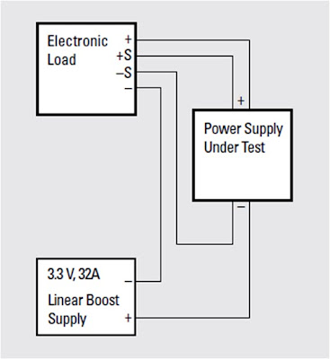
An effective solution for low voltage electronic load operation, right down to zero volts, for the electronic load’s full rated current, is to connect a low voltage boost power supply in series with the electronic load’s input. An example of this set up is depicted in Figure 2.


Figure 2: Zero volt DC electronic load set up

The electronic load now sees the sum of the boost supply’s and DUT’s voltages. Selecting a boost supply having adequate voltage will assure the electronic load will be able to operate at full performance at full current, even when the voltage at the DUT is zero. There are a few things that need to be paid attention to:
  • The electronic load needs to dissipate the total power of both the boost supply and DUT
  • The DUT needs to be adequately safeguarded against reverse polarity if the electronic load is inadvertently turned on too hard
  • The electronic load’s voltage sensing must be able to accommodate the extra voltage difference between the electronic load and DUT, due to the boost supply voltage
  • The boost supply ripple and noise (PARD) can contribute to noise measurements made on the DUT


Due to these considerations not all electronic loads may be well suited for zero volt operation with a boost supply so it is necessary to validate if a particular electronic load under consideration can be applied in this manner first.  Further details about zero voltage load operation as well as using Agilent N3300 series DC electronic loads for this purpose are described in product note “Agilent Zero Volt Electronic Load”, publication number 5968-6360E. Click here to access

Wednesday, October 31, 2012

What happens if remote sense leads open?

Remote sense is a feature on many power supplies that allows the power supply to regulate its output voltage right at your load (“remotely”) instead of at the power supply output terminals. Use remote sense when you want to compensate for load lead voltage drop caused by load current flowing in your load leads. This is accomplished by using a pair of remote sense leads that are in addition to your load leads. See an example in Figure 1. The power supply uses the voltage across the remote sense lead terminals to sense (measure) the voltage at the load terminals and regulate the voltage directly across the load by adjusting the output terminal voltage. Refer to this post I wrote last year on remote sense:
https://powersupplyblog.tm.agilent.com/2011/08/use-remote-sense-to-regulate-voltage-at.html


Remote sense leads could be accidentally left open, or once connected, one or both leads could inadvertently become open. I have had users of our power supplies testing very expensive devices under test (DUTs) ask me what would happen to the output voltage if a sense lead wired in a system opened; they were worried about subjecting their very expensive DUT to excessive voltage.

To understand why this is an important consideration, it is necessary to better understand the role of the sense leads. To regulate its output voltage, a power supply uses internal circuitry that acts as a feedback loop. The voltage is set to a particular value and the feedback loop monitors (measures) the voltage across the sense terminals and compares it to the setting. If it is too low, the loop circuitry increases the output voltage. If it is too high, the loop circuitry decreases the output voltage. So the actions of this loop result in the output voltage settling (being regulated) at a value such that the sense lead voltage equals the voltage set point.

If one or both of the sense leads is open, the feedback loop is broken and incorrect voltage information is sent to the loop. With an open sense lead, the sense voltage is typically near zero. The loop thinks the output voltage is too low and responds by increasing the output voltage. But this does not result in a corresponding increase in the sense lead voltage since the wire is broken so the loop increases the output voltage more. This continues until the value is increased to the maximum amount possible, which is usually somewhat higher than the maximum rated voltage of the power supply and very much beyond the desired set point. This could easily damage the DUT!

The scenario described in the previous paragraph is what would happen if no action was taken to prevent a runaway output voltage due to an open sense lead. Agilent power supplies have an internal circuit, called open sense protection, that prevents the output voltage from rising significantly above the set voltage if one or both of the remote sense leads is open. In fact, with one or both sense leads open, the output voltage of most Agilent power supplies will rise only 1 or 2 percent above the setting. Additionally, some Agilent power supplies can detect an open sense lead and respond by shutting down the output and alerting the user by changing a bit in a status register.

Note that this open sense protect circuitry is in addition to and independent from the over-voltage protection (OVP) circuitry common on most Agilent power supplies. OVP is a setting that is separate from the output voltage setting. If the actual output voltage exceeds the OVP setting, the OVP will shut down the output to protect the DUT.

Thursday, August 25, 2011

Use Remote Sense to Regulate Voltage at Your Load

Have you ever set your power supply output voltage to a particular value and found the voltage at your load was lower than you expected? If this was acceptable for your test, then you probably just left it alone. But if you wanted the voltage at your load to be equal to the voltage you set, then you should have used remote sensing.

Remote sensing is a feature on many power supplies that allows the power supply to regulate the voltage right at your load (“remotely”). This is accomplished by using a set of remote sense leads that are in addition to your load leads. The power supply uses the voltage on the remote sense lead terminals to sense the voltage right at the load terminals and regulate the voltage right at the load by adjusting the output terminal voltage.

Consider the example in Figure 1 showing a power supply set for 5 V, the desired voltage at the load. If the load is located six feet away from the output terminals, and you are using 14 AWG wire (about 2.5 mΩ/ft), each load lead will have about 0.015 Ω of resistance. If 10 A is flowing through the load leads, each load lead will drop about 0.15 V (10 A x 0.015 Ω) for a total drop of 0.3 V. When the power supply regulates its output voltage right at the output terminals, the result at the load is 4.7 V instead of the desired 5 V.


Figure 2 shows the same setup using remote sensing. The remote sense terminals are connected to the load at the points where you want the 5 V setting to be regulated. In this case, the power supply regulates 5 V at the load by adjusting its output voltage to 5.3 V to make up for the drops in the load leads. It does this by using the voltage across the sense leads as part of the feedback loop inside the power supply to adjust the voltage on the output terminals. The purpose of the power supply is to keep the sense lead voltage constant at the setting; the power supply changes the output terminal voltage based on the sense terminal voltage. The input impedance of the sense terminals is high enough to prevent any significant current flow into the sense terminals – this makes any voltage drop on the sense leads themselves negligible.